well here it's les than 300 bucks ! Same price than the RCF of above !
Would b glad to read a review of those with the 18thSounds 1460A and the BMS4592ND, some Oberton and new BC compressions...
Would b glad to read a review of those with the 18thSounds 1460A and the BMS4592ND, some Oberton and new BC compressions...
Last edited:
Although I'm a fan of Faital Pro driver and HF10AK is my favorite one-inch CD,

Indeed, one of the best 1" i heard so far.
for fun, make a K-tube ~20cm in length with a half-ellipse based slot. A quick rolled paper tube cut with scissor might do for impressions. A baffle at the driver exit could reinforce the low end.
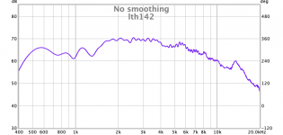
I tried to measure the hf1440 with rew in my livingroom on XT1464 and LTH142 respectively. The measurments are not calibrated, not at the same signal level, and generally quick and dirty (family away for the weekend so I can divide a room for new daughter, not much time for playing) Gating 6 ms. Lots of nearby surfaces. Attaching them in case anyone is interested.
Attachments

Is that without EQ? If so, you've got 450-10k - 3dB i.e. 4,5 octaves only needing a low Q 3 dB attenuation around 3k - cool!
//
//
No EQ, just raw drivers. I found them used with horns from Denmark and a pair of 15pr400 used from Sweden. Good that the graphs look easy to work with - I'm trying to "design" my first pair of speakers and have never done a crossover=)
The graphs look rather similar to me, so I will go with the xt1464 since discussion here gives the impression that it is slightly preferred to lth142, does this seem resonable?
The graphs look rather similar to me, so I will go with the xt1464 since discussion here gives the impression that it is slightly preferred to lth142, does this seem resonable?
You keep track fo this?
https://www.diyaudio.com/forums/multi-way/338806-acoustic-horn-design-easy-ath4-265.html#post6768137
//
https://www.diyaudio.com/forums/multi-way/338806-acoustic-horn-design-easy-ath4-265.html#post6768137
//
I tried to measure the hf1440 with rew in my livingroom on XT1464 and LTH142 respectively. The measurments are not calibrated, not at the same signal level, and generally quick and dirty (family away for the weekend so I can divide a room for new daughter, not much time for playing) Gating 6 ms. Lots of nearby surfaces. Attaching them in case anyone is interested.
Hi, I am wondering about this bump step around 1k3 in both horns. The second driver measures the same? Seems not to be a linear driver.
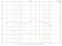
Compare this to the ND3N attached to LTH142. Much superior.

Could it be a measurement artifact? It's not in chebums plots. Those were my first attempts at using REW.
TNT: I have been following ath4-thread, but am trying to make my first speaker build as simple as possible with an off the shelf waveguide. This is tempting though Original Prusa MINI+ - Prusa Research
TNT: I have been following ath4-thread, but am trying to make my first speaker build as simple as possible with an off the shelf waveguide. This is tempting though Original Prusa MINI+ - Prusa Research
Hi, I am wondering about this bump step around 1k3 in both horns.
I see it too. ATH4 optimised horn. 1M.
Interestingly enough there is a peak in the impedance plot at this frequency in the Faital Pro data, but no response irregularity.
Attachments
Last edited:
I have also suspected that this bump is related to the impedance side peak which is very high (about 40 Ohms).
What amps were used for the measurements - voltage source? Maybe a current source would help or try to use a high value series resistor with the driver.
Or were any capacitors used during measurement to protect the driver?
Sadly manufacturers to not provide much info hoe their curves were generated (equipment, horn, smoothing, etc.).
Voltage source for my measurements. No protective cap. It would be interesting to redo with some series resistance.
Same here, voltage source, no protection capacitor.
I've cleaned all hobby things away since my wife and children are coming back from the countryside soon - will spend the time until my next opportunity for play presents itself reading this: Impedance Compensation
I've cleaned all hobby things away since my wife and children are coming back from the countryside soon - will spend the time until my next opportunity for play presents itself reading this: Impedance Compensation
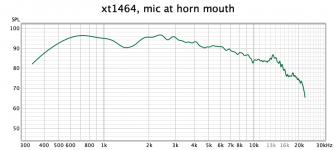
I redid the measurements with the lastest rew 5.20 beta, 2 ms window, mic calibration and mic at horn mouth, there is still a 6 dB dip centered around 1,3-1,4 kHz. Ärsch!
The dip seem to occur exactly where the driver's impedance side peak is. If we assume simply that P = U**2 / R then the voltage source amp might provide much less output power P into the bigger load R resistance.
What I would try now is a setup with amp out following first a 10 ohms parallel resistor and after this an 100 ohms resistor in series with the driver.
The difference would then be about 108 (normal) to 140 (peak) and without this setup 8 to 40.
- Home
- Loudspeakers
- Multi-Way
- HF1440 New Ring Compression Driver from Faital Pro.