TONI G, I missed answering one of your queries and that is you do not have to seal the laminations in the areas that you have coloured red. I would also add that there is no point in removing the diaphragm just to apply the gasket compound. This is only a suggestion to be followed when fitting a replacement diaphragm.
Not to upset the general spirit of tuning up passive notch filters, but for those wondering what the DSP crossover settings would be for a recently produced AMT-1 which is fully broken-in (in the following case using a 1979 Klipsch Cornwall bass bin with the back against a wall and the AMT-1 referenced to the front of the cabinet), the following PEQs were used to flatten the AMT-1 + Cornwall bass bin (two-way) response, crossed at ~700 Hz using first order filters (using an EV Dx38 crossover):
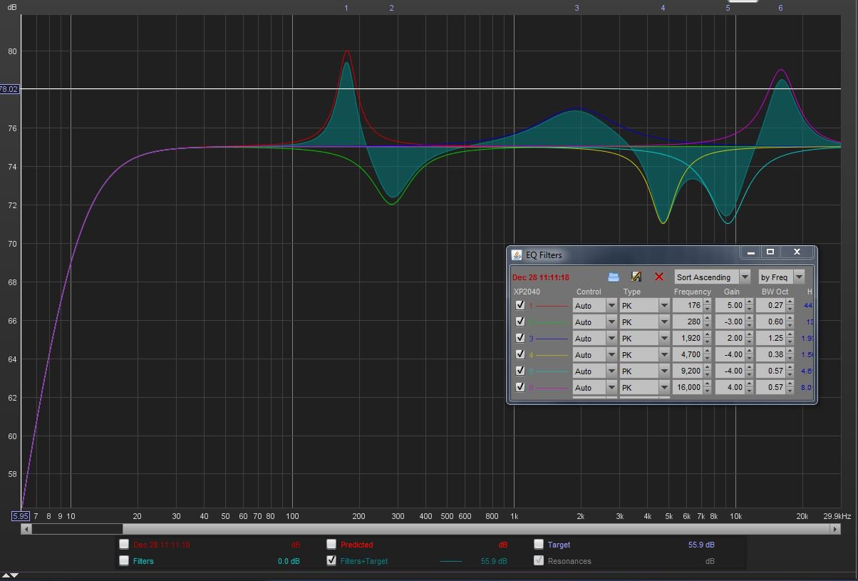
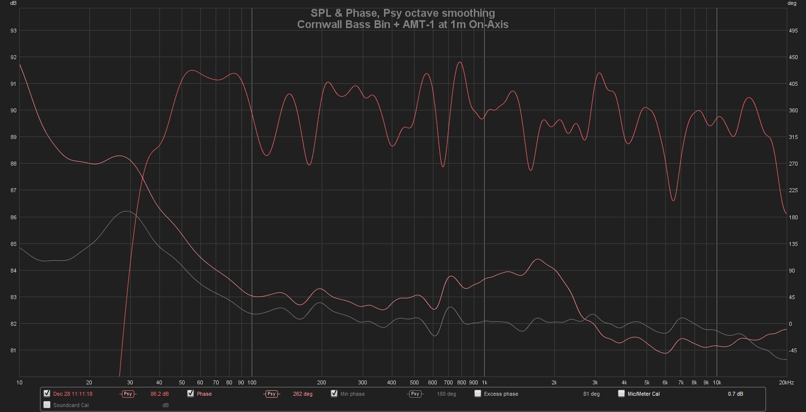
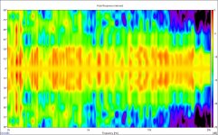
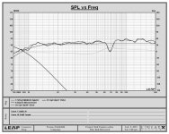
These settings were determined in REW using a microphone placed 1 metre in front of the loudspeaker assembly with the microphone's axis just below the centerline of the AMT-1 and pointed up at a 45 degree angle. There is plenty of absorption material on the floor between the microphone and the loudspeaker for taking polar measurements (0 to 90 degrees off-axis). The resulting on-axis SPL and phase response is as shown below, with the min phase trace in gray color. The vertical resolution is 1 dB and 45 degrees of phase grid lines, as shown:
Chris
When the ESS HEIL AMT is equalised to correct the rising response characteristic, the average SPL levels vary from +- 3dB from 2 kHz to 22 kHz based on a 96.5dB average at one metre for a 2.829 volt input level.* The characteristic ' peaks' at 6 and 7kHz together with a null at 6kHz, are just acoustical interference artefacts and are not indicative of problems with the AMT that need correction. TONI G did supply details of the plans he based his speaker on, in his opening post and this information allows me to suggest that the values of the resistors in the L pad should be 2.75 ohm for the series resistor and 9.1 ohm for the // resistor. The series input resistor is not required.
* for #2336 CLIOwin 7. Resolution1/48 Octave. 1/12 Octave smoothing.
* for #2336 CLIOwin 7. Resolution1/48 Octave. 1/12 Octave smoothing.
In my experience, ±3 dB isn't terribly good in terms of hi-fi listening at those frequencies (just like Toole reports), which is why I provided the measurements/corrections above at ±1 dB resolution. The closer to ±1 dB that you can get, the subjective listening experience improves--dramatically.
YMMV.
Chris
YMMV.
Chris
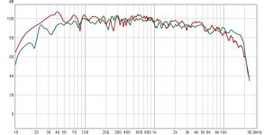
Hello, Here are the loudspekers curve response in the lisening point (red) and the L Chanel at 1m. (I use a subwofer too)
The crossover is the same of the Troels G. ATS loudspeakers. Jenzen-ATS Im only change the tweeter LCR and the first resistence. In any case I dont want make a great change in the crossover, only try to integrate the ESS in the actual configuration. I most say that the ATS original tweeter (Berilium SS) sound great but, in the other hand, the ESS have a special amb magic personality.
The crossover is the same of the Troels G. ATS loudspeakers. Jenzen-ATS Im only change the tweeter LCR and the first resistence. In any case I dont want make a great change in the crossover, only try to integrate the ESS in the actual configuration. I most say that the ATS original tweeter (Berilium SS) sound great but, in the other hand, the ESS have a special amb magic personality.
Attachments
Just a little subjective review of these amazing drivers ..
I am in my office today listening to the 'Goodbye Yellow Brick Road' 40th Anniversary remaster (44K FLAC) Just had it on in the background while at the computer. I have played this album 100s of times going back to first getting it on CD in 1984/5.
The sound now ... so full and rich .. the piano is beautiful. On 'Love Lies Bleeding' I never realized the little flute stabs towards the end are actually a Mellotron. On this setup you can hear it clearly. The distortion in the kick drum on 'I've Seen That Movie Too'. The amazing string arrangements in the stereo field .. huge. The growl of the Moog bass on 'All The Young Girls Love Alice' .. where has that been all my life?")
My office system is modest to say the least .. The big ESS is mated to a HiVi D8.8 woofer in a sealed cabinet. The amp is an old Kenwood 5.1 receiver .. just using the direct inputs for access to the power amps. It's fed by an original MiniDSP 2x4 getting its source from a PC with a Behringer UCA222 USB Interface. The cost of drivers themselves outweigh all the other components .. but this is some good hi-fi.
I've been tuning the MiniDSP by ear mostly and have landed at 1K as the crossover point using 24dB Butterworth filters. I'm pulling out 3db at 4800Hz with a Q of 4.3. I also have a high shelf starting at 11.5KHz with a gain of -2.3 and a Q of .3 (very shallow) to tame the high end ..
The previous top to this bass cabinet was a B&G Neo3 and Neo8 passively crossed .. then crossed to the HiVi with the MiniDSP. I loved that setup as well .. but the ESS is another level.
If you bought a pair on sale .. build something! The MiniDSP is down to $80 if you want to go 2-way. Play with them active first then decide if you want to build crossovers.
Biggest question ... what to play next.
I am in my office today listening to the 'Goodbye Yellow Brick Road' 40th Anniversary remaster (44K FLAC) Just had it on in the background while at the computer. I have played this album 100s of times going back to first getting it on CD in 1984/5.
The sound now ... so full and rich .. the piano is beautiful. On 'Love Lies Bleeding' I never realized the little flute stabs towards the end are actually a Mellotron. On this setup you can hear it clearly. The distortion in the kick drum on 'I've Seen That Movie Too'. The amazing string arrangements in the stereo field .. huge. The growl of the Moog bass on 'All The Young Girls Love Alice' .. where has that been all my life?
My office system is modest to say the least .. The big ESS is mated to a HiVi D8.8 woofer in a sealed cabinet. The amp is an old Kenwood 5.1 receiver .. just using the direct inputs for access to the power amps. It's fed by an original MiniDSP 2x4 getting its source from a PC with a Behringer UCA222 USB Interface. The cost of drivers themselves outweigh all the other components .. but this is some good hi-fi.
I've been tuning the MiniDSP by ear mostly and have landed at 1K as the crossover point using 24dB Butterworth filters. I'm pulling out 3db at 4800Hz with a Q of 4.3. I also have a high shelf starting at 11.5KHz with a gain of -2.3 and a Q of .3 (very shallow) to tame the high end ..
The previous top to this bass cabinet was a B&G Neo3 and Neo8 passively crossed .. then crossed to the HiVi with the MiniDSP. I loved that setup as well .. but the ESS is another level.
If you bought a pair on sale .. build something! The MiniDSP is down to $80 if you want to go 2-way. Play with them active first then decide if you want to build crossovers.
Biggest question ... what to play next.
Biggest question ... what to play next.
LOL this is funny I was using the same CD to check mine out! There is always Mad Man across the water "All the Nasties "some Steely Dan Everything Must Go "Pixeleen" or "Lunch with Geena", Allan Parsons Project, some Supertramp. They really are nice drivers!
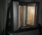
I have tried several materials, such as felt, on the sides of the AMT. In the photos the material that I am proving now, wood. Each material offers a different result. Can someone share experiences of this kind with good results?
What are you trying to accomplish?
What are you trying to accomplish?
As I said at the beginning of the thread, my wish is to solve the "sibilance" problems that, in my opinion, affect my ESS. I have read here and in other web sites different solutions. Some solutions acting on the design of the passive crossover and others acting on the surface (the V shaped area) with differents absorbent materials. I'm experienced with all possible solutions. I have confirmed that applying different materials in the V area around the diaphragm significantly changes the perceived response (for better or for worse). It is true that these solutions are not ideal since they are not "selective" with problematic frequencies.
I hope to soon receive an electric inductance meter to auto build a coil with a value of 0.065 mH to apply a solution that has been exposed in this thread (I have not found coils with that low value for sale in specialized stores).
I have also commented that my intention is not to realiazar a new project of loudspeakers (including the design of a crossover) but to try to adapt the ESS to the current loudspeakers (ATS of Troels Gravensen).
low inductance coils
Hi
I saw in some magazine that Mundorf in Germany started to make low value coils.
Another thing, as far as I can remember in the frequency plots I have seen of the AMT1, it is only in the 0 degree plot that the spike at 5 kHz is an issue.
My plan is to put some absorbant material in a small strip in front ( maybe in the back too) to see if it can remove that spike.
I guess it depends on the material what frequence it absorbs. And on how wide and thick (deep) the strip is. Probably also at what distance to the diaphragma it is placed.
Any idea what would be the best material?
best regards
Uwe
Last edited:
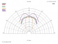
I don't see that at all: normalized polar plot to 90 degrees of an in-room AMT-1 EQed relatively flat using an EV Dx38, below:...Another thing, as far as I can remember in the frequency plots I have seen of the AMT1, it is only in the 0 degree plot that the spike at 5 kHz is an issue...
If there were only an on-axis issue, it would show up as a big roll-off outside of on-axis at 5 kHz. I don't see anything like that...
Chris
Attachments
Another thing, as far as I can remember in the frequency plots I have seen of the AMT1, it is only in the 0 degree plot that the spike at 5 kHz is an issue.
I am using a passive 5.5K notch and don't have a hole in the response off axis as well, that's the only EQ I have on them.
Rob
Attachments
Last edited:
I hope to soon receive an electric inductance meter to auto build a coil with a value of 0.065 mH to apply a solution that has been exposed in this thread (I have not found coils with that low value for sale in specialized stores).
These companies will wind custom coils to any value you want ..
North Creek Custom Wound Inductors
CROSSOVER INDUCTORS CUSTOM WOUND TO PERFECTION - .
Before I started to physically modify the drivers, I would try building a prototype with an active crossover. Used ones are cheap. Find the crossover points and EQ that you are happy with .. then model out the passive crossover (although once you go active .. it's hard going back)
I am using a passive 5.5K notch and don't have a hole in the response off axis as well, that's the only EQ I have on them.
Rob
hello, can you report the exact values of your network nocht? In the link that you provided, the values are not clearly seen.
These companies will wind custom coils to any value you want ..
North Creek Custom Wound Inductors
CROSSOVER INDUCTORS CUSTOM WOUND TO PERFECTION - .
Before I started to physically modify the drivers, I would try building a prototype with an active crossover. Used ones are cheap. Find the crossover points and EQ that you are happy with .. then model out the passive crossover (although once you go active .. it's hard going back)
thanks for the info.
Hi
I saw in some magazine that Mundorf in Germany started to make low value coils.
Another thing, as far as I can remember in the frequency plots I have seen of the AMT1, it is only in the 0 degree plot that the spike at 5 kHz is an issue.
My plan is to put some absorbant material in a small strip in front ( maybe in the back too) to see if it can remove that spike.
I guess it depends on the material what frequence it absorbs. And on how wide and thick (deep) the strip is. Probably also at what distance to the diaphragma it is placed.
Any idea what would be the best material?
best regards
Uwe
I have tried with felt, cardboard and wood. I have not taken measurements. On hearing, the felt reduces all high frequencies (IMHO) too much. The problem with this type of solution is that it is not "selective" at the problematic frequencies. Knowing the absorption coefficients of these materials is not easy either. For this reason, I have also asked if other people have more and better experience with this solution.
Hello TONI
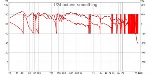
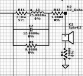
Here I blew it up to make it easier read. It is a .075u with a series .33 resistor to lower the Q and broaden the notch. To make the .075u I purchased a .100u and took some windings off measuring on a WT2. The DCR of the coil is about 60 mili ohms to get closer to the target of .4 ohms total. I also attached a measured vs. predicted so you can see the on axis response is with the notch and the active 24Db L/R crossover. The others resistors were bring up the DCR overall to about 8 ohms. I loose about a 1db to or so overall.
Even though there is still a rising response it sounds good to me as the overall power response tends too flattens this out.
Rob
Attachments
I have tried with felt, cardboard and wood. I have not taken measurements. On hearing, the felt reduces all high frequencies (IMHO) too much. The problem with this type of solution is that it is not "selective" at the problematic frequencies. Knowing the absorption coefficients of these materials is not easy either. For this reason, I have also asked if other people have more and better experience with this solution.
Did you see this thread, specifically posts #33 and #34 where they discuss how to fix the 5 KHz and 12 KHz problems?
To Heil AMT or not to Heil at $140, that is the question?
- Home
- Loudspeakers
- Multi-Way
- ESS AMT tweeter. Help for correct use