I'm following this thread as I'm about to start building a set of synergy style horns.
Found the Tom D quote I had saved:
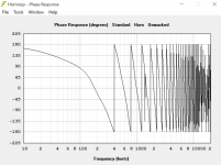
" A crossover hint. Next time you have your software open, model two band pass filters to make a pretend upper and lower speaker. Examine the phase response for each. Notice that the phase doesn’t approach zero until quite a ways above the low corners.
Our style xover ideally ends with a flat phase response like there was no crossover at all. So, what one can see is that if one were going to “shove” the two bandwidths closer together to knit them so that the phases were say around 90 degrees apart , that you have to be past the low corner of the upper driver. Also the less phase shift the corner has (shallower) the less rapidly the phase is changing.
A changing phase is changing time.
This is why I have mentioned the lower response corner and phase of the bms driver, it makes it easier to do. If you examine the group delay for the sum and displace the upper driver to the rear, one can justify the GD to be equal. When you have the right electrical part and the right physical offset, it looks acts sounds like one driver covering that band. I can’t tell you what slopes to use because you end up with something with no name, it has to be adapted to the acoustic magnitude and phase responses of the sources. I can say that usually I can get away with something reaching a 4th order or higher electrical high pass for the compression driver. Best, Tom Danley "
Found the Tom D quote I had saved:
" A crossover hint. Next time you have your software open, model two band pass filters to make a pretend upper and lower speaker. Examine the phase response for each. Notice that the phase doesn’t approach zero until quite a ways above the low corners.
Our style xover ideally ends with a flat phase response like there was no crossover at all. So, what one can see is that if one were going to “shove” the two bandwidths closer together to knit them so that the phases were say around 90 degrees apart , that you have to be past the low corner of the upper driver. Also the less phase shift the corner has (shallower) the less rapidly the phase is changing.
A changing phase is changing time.
This is why I have mentioned the lower response corner and phase of the bms driver, it makes it easier to do. If you examine the group delay for the sum and displace the upper driver to the rear, one can justify the GD to be equal. When you have the right electrical part and the right physical offset, it looks acts sounds like one driver covering that band. I can’t tell you what slopes to use because you end up with something with no name, it has to be adapted to the acoustic magnitude and phase responses of the sources. I can say that usually I can get away with something reaching a 4th order or higher electrical high pass for the compression driver. Best, Tom Danley "
That quote was from here. A good quote and fairly accurate in terms of what they are actually doing...except for the 4th order high pass on the compression driver part--there isn't any high pass filter affecting the SPL crossover point (about 1350 Hz), but there is a big attenuating PEQ on that channel, as stated above.
The crossover phase discussion is correct.
Chris
The crossover phase discussion is correct.
Chris
To drift back to the questions asked by the OP, the discussion about the need for midrange drivers is basically precluded if using your 2" compression drivers. The reason for the mids in the Danley designs is for:...Lots of degrees of freedom in Unity designs...one that seems particularly difficult for me to get my head around is phase/time alignment between the mids and compression drivers.
What's the workflow like for that? If I use those N850s crossed at 650Hz, 24 dB/octave, and then choose the horn outer dimensions based on intended pattern control cutoff... then I can model the compression drivers and mids separately in hornresp and shift the mid entry points until they match phase at the crossover point... right? Any other gotchas here? Easier ways to do this?
1) higher power handling (PA duty), and
2) overall loudspeaker phase control vs. frequency for multiple loudspeaker array-ability (i.e., stacking for coverage greater than 50 degrees)
Since a typical 2" compression driver is good down to 450 Hz in terms of its phase performance in a typical MEH, there is no need for trying to shoe-horn them in. In fact, you create issues with the added off-axis ports for the mids so close to the apex compression driver at the horn's throat, not to mention the geometric packaging problems getting the mids so close to the compression driver. If you want a two-way driver, I'd instead recommend BMS 4592ND dual-diaphragm compression drivers, then you get all the advantages of the separate diaphragms for midrange and tweeter without any downside for added off-axis holes and geometric interference problems.
We've discussed the need for flat phase vs. frequency a little bit, and the OP may want to know why that's important. That would be a fair question, but it was subsequently indicated that the OP is intending to use digital FIR filters to flatten phase vs. frequency. So that discussion will probably not be required.
The discussion of "phase" in the quote above is really a discussion of setting the notch frequency of the off-axis ports to the throat bounce distance. That's something that Hornresp does pretty well, but Hornresp doesn't tell you the size of the off-axis ports, nor where to place the centerline vs. leading edge of the ports to achieve the desired frequency. I've found that the ports need to be positioned so that the leading leading of the port is at the calculated distance of the Hornresp predicted response--not the centerline of the port.
Another issue is the area of the ports. The OP may not know that the diaphragm area to port area of the driver (commonly called the "compression ratio" of the ports) directly determines the efficiency of the port/drivers. The higher the compression ratio, the lower the efficiency. That offsets the desire to make the ports too small, but the effect of the ports on the polar coverage at the 1/4 wavelength axial frequency also is a tradeoff. I've found that 10:1 compression ratio is about as far as you want to go. Danley uses between 6-7 maximum compression ratio on the off-axis ports. The farther that the ports are located from the compression driver throat, the less their effects are, and midrange off-axis ports are a problem in that respect, since they are so close to the compression driver throat. This is another reason to avoid using midrange drivers and going directly from 2" compression driver throat to woofer off-axis ports, but set at an axial distance of around 4" from the throat--it disturbs the polar coverage the least.
The use of reflex ports on the aperture of the MEH, as found in the Danley designs, I've found these ports are part of the passive crossover scheme, but not so much an active crossover scheme. Those reflex ports are tuned to between 100-200 Hz or slightly lower, so the effect that they have is easily EQed out using a DSP crossover, and not using reflex ports on the MEH improves the polar coverage of the horn. (Danley really doesn't post polar coverage vs. frequency of their MEHs, so most people are not cognizant of those tradeoffs. Danley's use of those ports is related to array-ability of the loudspeakers using passive crossovers only, and not really home hi-fi.).
We have discussed the need to use lower order low pass crossover filters in order to preserve overall phase, the need to pay attention to the phase rotation vs. frequency of drivers as the frequency decreases in order to set the lowest crossover point of the drivers, and the offsetting effects of putting the off-axis ports too close to the throat of the MEH. These are design tradeoffs.
Also, you will find that high-pass/low pass crossover filter frequency overlap will need to be increased using MEH designs. I find that using first order crossover filters automatically takes care of the phase/frequency and the polar coverage/frequency issues. I recommend first trying the high pass crossover frequency at about 50 Hz below the low pass point, as a start. You will need to iterate this to find the best overlap to use for your horn coverage angles and off-axis ports.
Chris
Last edited:
Has there been mention of how well the array of ports integrates when the horn has a wider profile? I could be wrong but I assume hornresp does a 1P analysis.setting the notch frequency of the off-axis ports to the throat bounce distance. That's something that Hornresp does pretty well,
Yes, I believe that you are worried about the simplification of the wave equation to one dimension (as I assume that Hornresp does, but we really don't know since the equations used are not explained in an analyst manual). Remember however that for straight-sided horns or horns with initially straight sides then flaring toward the mouth, the simplification of the wave equation is still valid in the straight-sided area of the horn. The Webster equation won't predict higher order modes (as Geddes points out), but it does do a credible job in terms of predicting the notch frequency of the off-axis ports.
Would I like to have a full wave equation simulator that's as easy to use as Hornresp? Yes. Do I believe that it would give me significantly better information for placing the off-axis ports in the straight-sided portion of an MEH? No.
The issue that you bring up--wider coverage--I've found to be an issue only as the coverage angle exceeds 90 degrees in one horn dimension. At some point, the "horn" is behaving more like a flat baffle, meaning the drivers might not integrate like they do in a horn. However, consider the following:
1) When drivers are arrayed within a quarter wavelength at the highest operating frequency, they integrate into one source (Danley has stated this, and we see the same results in dual slit experiments).
2) Drivers mounted within 1/4 wavelength also seem to integrate their polars, up to the point that the frequencies "detach" from the flat baffle or the horn's walls. This is frequency-dependent, and can be seen in the polar plots of horn/drivers and flat baffle/discrete drivers within 1/4 wavelength at the highest frequency of interest.
Chris
Last edited:
Cask05: your comments about loading mids into a horn are probably valid. However, being able to buy a pair of genuine Unity horns (trashed albeit) for $700 delivered is not to be sneezed at ") They sound great, all the more so with a recent re-EQ. Now that i have reliable measuring gear again, it remains to be seen* what room correction can be done in listening room with the acoustics of a mausoleum
They sound great, all the more so with a recent re-EQ. Now that i have reliable measuring gear again, it remains to be seen* what room correction can be done in listening room with the acoustics of a mausoleum
*"remains to be seen" would have been at the viewing, before being moved to said mausoleum. A little bit of seasonal humor there.
They sound great, all the more so with a recent re-EQ. Now that i have reliable measuring gear again, it remains to be seen* what room correction can be done in listening room with the acoustics of a mausoleum *"remains to be seen" would have been at the viewing, before being moved to said mausoleum. A little bit of seasonal humor there.
Last edited:
My comments have been directed to the OP who is contemplating a new-start MEH of his own making.
Refurbishing Unity horns is another endeavor that can be facilitated through benchmarking with Synergy series MEHs. Clearly, I can talk about that subject but I think that might dilute the objective of the OP here...unless he wants to go in that direction, too.
Chris
Refurbishing Unity horns is another endeavor that can be facilitated through benchmarking with Synergy series MEHs. Clearly, I can talk about that subject but I think that might dilute the objective of the OP here...unless he wants to go in that direction, too.
Chris
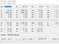
The B&C 8PE21 is looking promising, even though all uses of it I've seen in a Unity so far are with a 1" compression driver and a higher intended low cut.
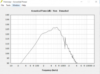
I'd like to get these to 115dB SPL within excursion limits, which the current model just barely does with two of them (graphs shown are for a single driver). Shrinking the back chamber (Vrc) from 10L to 1L drops response at 100Hz about 6dB while leaving the rest of the response untouched. Raising it as high as 100L doesn't even change the response on the graph until down around 40-60Hz, which I guess is nice so that there's some flexibility in construction to just make whatever sized "big" back chamber is convenient and leave it at that.
Response is *not* flat within the passband, which I'm OK with since I'm going to be doing plenty of other EQing if the system hits overall SPL targets. I'm wondering what else I could try to get better than 110dB per driver at max excursion. The fact that it's excursion limited seems to suggest that in that region, port size will *not* affect efficiency much. Hornresp agrees. Lengthening the throat adapter (Lp) does shift the response hump downwards.
Any ideas which parameters here might help level out the response, or narrow the pass band so that I can sacrifice bandwidth up around 6-700Hz for the sake of efficiency lower down?
Attachments
I should rephrase what I said about port efficiency: @Cask05 it makes sense to me that too small of a port/too high a compression ratio would limit efficiency. I'm saying that it doesn't seem like I could gain much back with a bigger port if I'm already excursion limited. I'd be happy to be wrong about that though.
I've got some 8pe21 sims flatter than that but same similar on the low end. High end is most affected by L.p. and Ap1 also Vtc but you really need to model as a throat ported OD to see that. A fair amount of bandpass peaking is unavoidable and then you get more roll off as you go below pattern control freq of the horn
The 8PE21 is very efficient. It has a very high efficiency/bandwidth product and so is suitable for loading. Your conical horn may not be achieving the most in that respect. However, it is still a good choice due to the directivity it offers.
Baffling, or another base radiation space assignment might be beneficial. I have found the 8PE21 to become quite loud on less than a Watt, crossed above 150Hz.
As far as excursion is concerned, these will happily go higher than the suggested 1mm.
Baffling, or another base radiation space assignment might be beneficial. I have found the 8PE21 to become quite loud on less than a Watt, crossed above 150Hz.
As far as excursion is concerned, these will happily go higher than the suggested 1mm.
I think that there is a reason why you are not finding midrange drivers used with 2" compression drivers--is due to the fact that you don't need the midrange driver, even at 115 dB/one mThe B&C 8PE21 is looking promising, even though all uses of it I've seen in a Unity so far are with a 1" compression driver and a higher intended low cut.
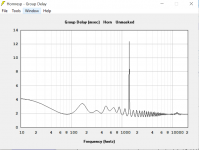
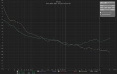
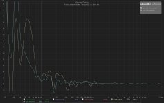
Below, you will see the phase and group delay plots of a stock SH-50 compared to the K-402-MEH w/BMS 4592ND. Remember the emphasis that Danley placed on phase which to me indicated the reason why the midrange drivers were used at all:
The SH-50 traces are in manila color, while the K-402-MEH's are in light blue.
The reason for the midranges--once you see the actual driver traces individually--shows that the primary reason for the mids in the SH-50 are for phase growth control of the apex 1" driver, since their contribution the SPL output of the SH-50 is just over one octave (520-1360 Hz). Once you see that your 2" compression drivers can easily cover this band without the phase shifts of a BMS 1" compression driver used on the SH-50, I think you might rethink the need for the extra mids, instead applying your efforts to a better horn profile and full range operation--like both the SH-50 and K-402-MEH provide.
Chris
Attachments
If you were running your MEHs at 125+ dBC all the time, I could see the need for the mids, as Danley is using them--extremely high power operation for PA duty (well above 115 dB). Personally, the max values of SPL at 1 m on-axis that I use them in the house is probably more like 105 dBC in the peaks, and about 83 dBC average (during loud demastering duty).
Chris
Chris
I'm intending a 2-way using just the 2" compression drivers and 8PE21s (or something similar if those turn out to be unsuitable, but I think I can make them work). Are we on the same page here? It sounds like you're telling me not to use any extra drivers between the bass and the 2" drivers, and I'm intending not to
I'm intending a 2-way using just the 2" compression drivers and 8PE21s (or something similar if those turn out to be unsuitable, but I think I can make them work). Are we on the same page here? It sounds like you're telling me not to use any extra drivers between the bass and the 2" drivers, and I'm intending not to
It's clear that my data and information posted in this thread has somehow upset you. My apologies. Please disregard my entries here.
Chris
Thanks Rob.
@Cask05, maybe I've been resistant to some of what you're saying because it's not what I was initially expecting, but I'm taking my time with it. For example, I thought I'd just be able to run with a sharp filter cutoff and go... but it does sound well worth my time to play around with lower orders.
One of the points I was confused on was which BMS driver you were talking about... I see now that the 4592ND is a *very* beefy 2" capable of a very low crossover point. Is that the one you're using in the K-402-MEH?
Regarding the graphs, it seems to me at a glance like both phase plots look pretty good, although you're right, there are qualitative differences. I'm not sure which one is "better". They both look fairly linear, with the K-402-MEH heading back towards 0 degrees as it goes up and the SH-50 going down.
Does the thread you linked on the Klipsch community show other horn profiles? I'm not attached to the double conical - at all. I'm planning on 3D printing so I should have TONS of flexibility with this. Lots of room in my living area as well. I just don't have a good place to start. What would a better profile look like? I get the general idea that exponential would load lower for the same outer dimensions while not being constant directivity. I guess I had a general idea that something SEOS- or oblate-spheroid-like would probably be a good idea but hadn't done much to model that far. Any experience to offer?
- Status
- This old topic is closed. If you want to reopen this topic, contact a moderator using the "Report Post" button.
- Home
- Loudspeakers
- Multi-Way
- Unity horn time alignment workflow