Long story … I have compared the impact of the voice coil inductance on the on axis SPL (on infinite baffle) for 3 woofers: Faital 12PR320, D.A.S. Audio 12P and Beyma SM212.
Therefore the SPL on axis of the TSP model of each woofer is simulated and compared.
Maybe some short general information first for a good understanding.
The TSP (Thiele Small Parameter) model is a constant piston model of the driver. That does mean, exclusive the impact of the cone breakup, but inclusive the inductance of the voice coil.
For an inductance of zero the on axis SPL of a TSP model is flat versus frequency. In practice, there is a fall off for higher frequencies due to the inductance.
It is interesting to compare the SPL of the TSP model with the SPL of the total driver to see the impact of the cone breakup. Especially for midrange evaluation it is very useful.
In attachement:
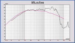
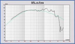
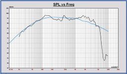
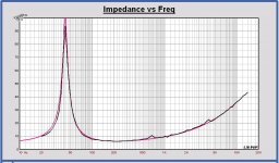
- For all plots, Faital in red, D.A.S. in green and Beyma in blue color.
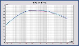
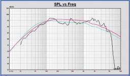
- The SPL plots: for each driver the SPL of the TSP model (in color) and the SPL of the datasheet (in black). With a little offset ( 1dB max ) on the datasheet SPL for a good mapping.
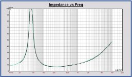
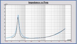
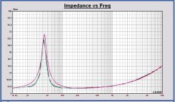
- The impedance plots for each driver, the model (in color) and datasheet (in black).
- All SPL and all impedances of the models in one plot to compare.
Some remarks:
- For the Beyma SM212 there is a big deviation between the SPL of the TSP model and the SPL of the datasheet already above 100Hz. For the other drivers there is a good mapping up to a few hundred Hz. Beyma specifies that the measurements are done on infinite baffle in an anechoic room. If this datasheet measurement is correct, I have my doubts about this driver. A nearfield measurement of this driver should be very useful. If that is flat, it is ok.
- Good relation between the impedance curves and the TSP of the datasheet. Except for the Beyma, a deviation around fs, strange…
- Comparing the SPL’s of the TSP models, the Beyma is most flat. The Faital is a little better than the DAS. The differences are low.
Taking all this in consideration at this moment, I choose for the D.A.S !!
Hopefully this was all a little bit understandable…
Therefore the SPL on axis of the TSP model of each woofer is simulated and compared.
Maybe some short general information first for a good understanding.
The TSP (Thiele Small Parameter) model is a constant piston model of the driver. That does mean, exclusive the impact of the cone breakup, but inclusive the inductance of the voice coil.
For an inductance of zero the on axis SPL of a TSP model is flat versus frequency. In practice, there is a fall off for higher frequencies due to the inductance.
It is interesting to compare the SPL of the TSP model with the SPL of the total driver to see the impact of the cone breakup. Especially for midrange evaluation it is very useful.
In attachement:
- For all plots, Faital in red, D.A.S. in green and Beyma in blue color.
- The SPL plots: for each driver the SPL of the TSP model (in color) and the SPL of the datasheet (in black). With a little offset ( 1dB max ) on the datasheet SPL for a good mapping.
- The impedance plots for each driver, the model (in color) and datasheet (in black).
- All SPL and all impedances of the models in one plot to compare.
Some remarks:
- For the Beyma SM212 there is a big deviation between the SPL of the TSP model and the SPL of the datasheet already above 100Hz. For the other drivers there is a good mapping up to a few hundred Hz. Beyma specifies that the measurements are done on infinite baffle in an anechoic room. If this datasheet measurement is correct, I have my doubts about this driver. A nearfield measurement of this driver should be very useful. If that is flat, it is ok.
- Good relation between the impedance curves and the TSP of the datasheet. Except for the Beyma, a deviation around fs, strange…
- Comparing the SPL’s of the TSP models, the Beyma is most flat. The Faital is a little better than the DAS. The differences are low.
Taking all this in consideration at this moment, I choose for the D.A.S !!
Hopefully this was all a little bit understandable…
Attachments
-
 SPL TSP model Faital 12PR320.JPG178.4 KB · Views: 551
 -
 SPL TSP model DAS 12P.JPG175 KB · Views: 549
 -
 SPL TSP model Beyma SM212.JPG172.7 KB · Views: 561
 -
 Impedance Faital 12PR320.JPG112.3 KB · Views: 490
 -
 Impedance DAS 12P.JPG111.1 KB · Views: 492
 -
 Impedance Beyma SM212.JPG105.1 KB · Views: 119
 -
 SPL TSP model ALL .JPG168.5 KB · Views: 123
 -
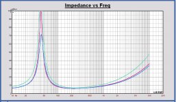 Impedances ALL.JPG108.6 KB · Views: 131
Last edited:
In my simulations the Faital is more flat than the D.A.S., which is in better relation with the voice coil inductance values, see post 61. Differences are low.Ok, here's a quick comparison using AJ Horn (black is the Faital 12PR320, red is the D.A.S. 12P). Box tuning as given in the list of the first post. AJ Horn models the effect of the voice coil impedance using the impedance values at 1kHz and 10kHz (taken from the curve charts). I'd say forget about the Le spec values. The D.A.S. actually seems to extend a bit higher than the Faital...
mbrennwa: I do not know exactly how your simulations where calculated since you only give volume and port area and length. But if my guesstimation is not too far off, your simulations look very nice in that regard, the group delay and phase is really smooth and should give very good sound.
I just checked the numbers you listed for the Faital 12PR320. 70 liters box and a port of 80cm2 and 12 cm length.
Your volumes and port sizes etc do not seem to exhibit any unwanted behaviour (I made an erronous assumption).
But the port is too small, not a problem with the power delivered from for instance the ACA, but if you try to power the speaker enough to reach xmax, the particle velocity in the port will reach 40m/sec.
Edit:
It seems that simply doubling port area and length (to 160cm2 and 24cm length) will fix this issue and pring the particle velocity down to a hair under 21m/sec. Group delay does look good at just over 14msec, but I am a sucker for that "closed box sound", and I prefer personally to keep group delay at 40hz around 10msec or less.
Again, this is nitpicking from my side. but a lower port resonance would negate the need for high pass to save the driver when driven hard, and also give a smoother roll off down low.
Last edited:
Long story … I have compared the impact of the voice coil inductance on the on axis SPL (on infinite baffle) for 3 woofers: Faital 12PR320, D.A.S. Audio 12P and Beyma SM212.
Therefore the SPL on axis of the TSP model of each woofer is simulated and compared.
Great!
For the Beyma SM212 there is a big deviation between the SPL of the TSP model and the SPL of the datasheet already above 100Hz.
I am assuming you used the TSP values listed in the datasheet. Could you revise these values so that the modeled impedance curve fits the measured curve? I have had more than one driver with TSP that were substantially different from those listed in the datasheet.

Hopefully this was all a little bit understandable…
Totally! Very useful!
In my simulations the Faital is more flat than the D.A.S. ...
If I got this right, your simulations were for an infinite baffle, right? My sims were for a bass reflex system. Maybe my bass-reflex tuning compensated for the Le effect. But I am not worried since the differences between the Faital and the D.A.S. are low.
mbrennwa: I do not know exactly how your simulations where calculated since you only give volume and port area and length. But if my guesstimation is not too far off, your simulations look very nice in that regard, the group delay and phase is really smooth and should give very good sound.
What other information would you need?
I just checked the numbers you listed for the Faital 12PR320. 70 liters box and a port of 80cm2 and 12 cm length.
Your volumes and port sizes etc do not seem to exhibit any unwanted behaviour (I made an erronous assumption).
But the port is too small, not a problem with the power delivered from for instance the ACA, but if you try to power the speaker enough to reach xmax, the particle velocity in the port will reach 40m/sec.
Edit:
It seems that simply doubling port area and length (to 160cm2 and 24cm length) will fix this issue and pring the particle velocity down to a hair under 21m/sec. Group delay does look good at just over 14msec, but I am a sucker for that "closed box sound", and I prefer personally to keep group delay at 40hz around 10msec or less.
Again, this is nitpicking from my side. but a lower port resonance would negate the need for high pass to save the driver when driven hard, and also give a smoother roll off down low.
Yes, a larger port sounds like a good idea. The exact bass-reflex tuning may need a few iterations to get right. I am all in for clean and tight bass!
...
What other information would you need?
...
Please, do not mind the grumpy Norwegian fellow, I am just nitpicking and being difficult as usual.
We can look at the numbers when we are certain about the driver.
The Faital 12PR320 has over 7mm xmax, the DAS 12P has 6mm, no problem for me at all, but is it important for others?
The Faital is available almost worldwide, the DAS is available only in Europe?
Should we take availability into account?
If not it seems the DAS is the winner on price in relation to performance?
If the Faital 15PR400 is anything to go by, the the 12PR320
Will be the better sounding driver. I know they Beyma SM and the Faital sounds so much better. Faital is used by Volti Audio and many top end manufacturers simply because it sounds so much better than the rest!
I know what driver i would use.
Will be the better sounding driver. I know they Beyma SM and the Faital sounds so much better. Faital is used by Volti Audio and many top end manufacturers simply because it sounds so much better than the rest!
I know what driver i would use.
Please, do not mind the grumpy Norwegian fellow, I am just nitpicking and being difficult as usual.
We can look at the numbers when we are certain about the driver.
The Faital 12PR320 has over 7mm xmax, the DAS 12P has 6mm, no problem for me at all, but is it important for others?
The Faital is available almost worldwide, the DAS is available only in Europe?
Should we take availability into account?
If not it seems the DAS is the winner on price in relation to performance?
For me the Faital is also ok. I have not looked to availability and price.
Technically, Qms of the DAS is higher, but xmax of Faital is 1mm better.
For me it is the same.
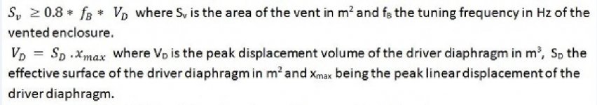
Concerning port area I use the R.Small vent requirement, see attachment.
Using that formula 120 cm2 would be enough, so 160cm2 will be very safe.
Attachments
I am assuming you used the TSP values listed in the datasheet. Could you revise these values so that the modeled impedance curve fits the measured curve? I have had more than one driver with TSP that were substantially different from those listed in the datasheet.
Good idea yes. I took the TSP as the truth. Tomorrow I will do
.If I got this right, your simulations were for an infinite baffle, right? My sims were for a bass reflex system. Maybe my bass-reflex tuning compensated for the Le effect. But I am not worried since the differences between the Faital and the D.A.S. are low.
That declares the difference. It is better to simulate it in the basreflex enclosure like you have done it.
Please, do not mind the grumpy Norwegian fellow, I am just nitpicking and being difficult as usual.
We can look at the numbers when we are certain about the driver.
The Faital 12PR320 has over 7mm xmax, the DAS 12P has 6mm, no problem for me at all, but is it important for others?
The Faital is available almost worldwide, the DAS is available only in Europe?
Should we take availability into account?
If not it seems the DAS is the winner on price in relation to performance?
So far, the Faital and DAS performance look very similar on paper. Personally, I'd trade 1mm Xmax over 33% Qms, so I'd prefer the DAS right now. The argument would be that Qms reflects the mechanical losses, which are especially non-linear at low excursions, whereas Xmax is important at high excursions -- and I prefer optimizing for low listening levels at home rather than for loud PA levels.
I'd expect D.A.S. will sell worldwide, either directly or via distributors. But let's see what they say in response to my inquiry.
Price: as I wrote before, price is important only after the technical arguments are settled.
If the Faital 15PR400 is anything to go by, the the 12PR320 Will be the better sounding driver. I know they Beyma SM and the Faital sounds so much better. Faital is used by Volti Audio and many top end manufacturers simply because it sounds so much better than the rest!
I know what driver i would use.
Not sure what you mean. The 12PR320 is better than what? Better than the D.A.S. driver? Did you compare them?
Last edited:
I am assuming you used the TSP values listed in the datasheet. Could you revise these values so that the modeled impedance curve fits the measured curve? I have had more than one driver with TSP that were substantially different from those listed in the datasheet.
I have looked to the Beyma SM212 w.r.t. the relation between the TSP and the curves of the datasheet.
I have made 2 TSP model versions:
- Version 1 using the TSP of the datasheet to be correct
- Version 2 using the impedance curve to be correct
In attachement:
SPL plot: version 1 in red, version 2 in green and datasheet curve in black
Impedance plot: version 1 in red, version 2 in green and datasheet curve in black
You can see that with version 2 the mapping of the SPL is better (above 100 Hz). So it looks like the curves of the datasheet are correct and the TSP are wrong.
Look how the TSP are changing, taking the impedance curve to be correct.
version 1 --> version 2
Qms: 5.31 --> 8.00
Qes: 0.41 --> 0.60
Qts: 0.38 --> 0.58
Fs: 43 --> 42 Hz
BL: 14.4 --> 11.5 N/A
This is a big difference. If version 2 is the correct specification, this driver cannot be used for the monkey box.
When you see all this, it doesn't give that much confidence...
Attachments
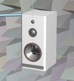
To create a cabinet model for the speaker study I did a fast edit of an existing drawing.
The size is W x H x D = 38 x 78 x 42 cm. The front panel is slightly rounded to the sides.
The port is rectangular with a size conform the last proposal of Kaffimann for the Faital 12PR320. The port can be modified later to a tube if wanted. Internal volume 70 L
First concept with Faital 12PR320 woofer (simulation available), Volt VM752 Midrange and Satori TW29BN tweeter.
Second concept with cone midrange, AE TD6M or other .
Does the Volt midrange need a separate chamber? If yes how large?. I see that this driver has a little waveguide. I cannot make a model of that, so correct off axis responses cannot be simulated now. I will do with the current model now. If we gonna use this midrange we have to do some off axis measurements for more accurate simulations.
In attach also the first model in Leap.
Please some feedback about shape, position of drivers,…
This is no proposal for a final concept, just trying to make the best model for the study with the information of today...
If this is ok, I can start with the study the coming days.
Attachments
Have you thought of doing a simulation with the mid and tweeter offset also? Here is a review of the Volt that may give some info.
Test Bench: Volt Loudspeakers VM752 3” Midrange Dome Driver | audioXpress
Test Bench: Volt Loudspeakers VM752 3” Midrange Dome Driver | audioXpress
To create a cabinet model for the speaker study I did a fast edit of an existing drawing.
The size is W x H x D = 38 x 78 x 42 cm. The front panel is slightly rounded to the sides.
The port is rectangular with a size conform the last proposal of Kaffimann for the Faital 12PR320. The port can be modified later to a tube if wanted. Internal volume 70 L
First concept with Faital 12PR320 woofer (simulation available), Volt VM752 Midrange and Satori TW29BN tweeter.
Second concept with cone midrange, AE TD6M or other .
Does the Volt midrange need a separate chamber? If yes how large?. I see that this driver has a little waveguide. I cannot make a model of that, so correct off axis responses cannot be simulated now. I will do with the current model now. If we gonna use this midrange we have to do some off axis measurements for more accurate simulations.
In attach also the first model in Leap.
Please some feedback about shape, position of drivers,…
This is no proposal for a final concept, just trying to make the best model for the study with the information of today...
If this is ok, I can start with the study the coming days.
Looking forward to this!
I'd suggest to offset the mid and tweeter from the baffle center to spread out the diffraction effects. Choosing the distances of the driver centers to the baffle edges according to the golden ratio seems to work well:
tweeter and midrange center to baffle left: 145 mm
tweeter and midrange center to baffle right: 235 mm
tweeter center to baffle top: 90 mm
The Volt dome midrange is closed. No need for a separate chamber.
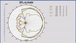
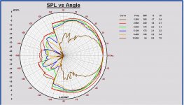
I am not a favorite of applying horizontal offset to the drivers on the front baffle, because it affects the horizontal polar diagram.I'd suggest to offset the mid and tweeter from the baffle center to spread out the diffraction effects. Choosing the distances of the driver centers to the baffle edges according to the golden ratio seems to work well:
You can see it the best on a horizontal polar diagram normalized to the on axis response. Look in attach to the polar diagrams with and without offset of the tweeter in the monkey box. You can see that in the range +/- 30 degrees horizontal, the SPL is less flat in the case of applying offset. You can make some improvement on the on axis SPL with offset, but off axis the SPL is less flat...
You may do it, but I don't support it.
Attachments
Thanks for the link. Yes, of course we have to take into account the offset between the acoustical centers of the drivers. We have to measure it once drivers are available. For my projects I measure the offset by comparing the start of the impulse of an mls measurment for each driver on IEC baffle at the same microphone position on axis. Like you also know, for a passive filter the compensation has to be included in the X-over design. For the study an estimation of the offset has to be done. Maybe I find more in the link, I will read it.Have you thought of doing a simulation with the mid and tweeter offset also? Here is a review of the Volt that may give some info.
Test Bench: Volt Loudspeakers VM752 3” Midrange Dome Driver | audioXpress
Last edited:
I'd suggest to offset the mid and tweeter from the baffle center to spread out the diffraction effects. Choosing the distances of the driver centers to the baffle edges according to the golden ratio seems to work well:
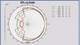
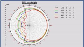
But .... looking to an horizontal offset on the midrange, that is much better
. We have to be honest.See the difference in attach.
Ok I will apply 4.5 cm horizontal offset on both tweeter and midrange.
Attachments
Last edited:
Look in attach to the polar diagrams with and without offset of the tweeter in the monkey box.
You can see that in the range +/- 30 degrees horizontal, the SPL is less flat in the case of applying offset.
Just a thought... If we add a waveguide to the tweeter, the baffle diffraction will become less important.
I have some adapter plates in the mail that should mate my Scan 6600 tweeters to a Monacor waveguide. I just happen to have those tweeters in my parts box, so they are free for experiments. I'll have a play with them and see what the waveguide does.
You can do already some on and off axis measurements (15 degree steps) of that tweeter mounted on a large baffle with and without that waveguide. In that way we know the transfer of the waveguide, which can be used in simulation. It will gives us a first impression. In Leap I can simulate the power response of the speaker with and without waveguide, but not the impact on the distribution of the power in the space, no off axis responses.
Before applying a waveguide a good investigation is needed. In most cases a waveguide is applied with a 7 or 8 inch midrange. With a 3 inch midrange it is different. And there is also the waveguide of the Volt 3 inch. We have to measure both tweeter (with and without waveguide) and midrange on a IEC baffle later.
Before applying a waveguide a good investigation is needed. In most cases a waveguide is applied with a 7 or 8 inch midrange. With a 3 inch midrange it is different. And there is also the waveguide of the Volt 3 inch. We have to measure both tweeter (with and without waveguide) and midrange on a IEC baffle later.
- Home
- Loudspeakers
- Multi-Way
- Open Source Monkey Box