I have made an LR4 filter 500 - 2500 Hz already to check some behavior, it is almost perfect on LR4 target.
...
A negative point of this LR4 filter at this time is a minimum impedance dip of only 3 Ohm at 38 Hz. I am afraid a serial resistance has to be placed with the first coil of the woofer filter, by using an air coil. Then I can get 4 Ohm as minimum impedance.
Pauls, your work is impressive, as always!
How does that 3 Ohm dip happen? Looking at the schematic I don't see anything that would allow a 3 Ohm path. Is this a resonance happening somewhere in the circuit?
Also digital filtering is an option. At this time I can design for miniDSP and Hypex platforms. And calculate biquad coefficients for orhers also.
Going active is always an option -- but as we have discussed earlier, I'd really like to have a completely passive version that would allow novices to get into the Monkey Coffin easily. Adding active filters later on should be optional (and I don't like digital filters due to excessive DAC/ADC conversions, but that's just me).
How does that 3 Ohm dip happen? Looking at the schematic I don't see anything that would allow a 3 Ohm path. Is this a resonance happening somewhere in the circuit?
Almost sure that the impedance dip is related to the current basreflex impedance shape.
Indeed a resonance dip of the equivalent electrical parallel capacitance of the basreflex impedance and the inductance of the woofer filter.
It is much less with closed box systems because the Q of the impedance peak is much lower.
It can be improved a little by increasing the serial resistance of the filter inductance, but that is at the expense of SPL loss.
Another and maybe better way is make the Q-factor of the basreflex system lower. In that way the system is more dampened.
It means a higher F3 but probably the same F6 (Kaffimann is a big fan of that
") ). We can make the cabinet volume for the basreflex also a little larger and decreasing the tuning frequency, that is also an option.
). We can make the cabinet volume for the basreflex also a little larger and decreasing the tuning frequency, that is also an option.: Kaffimann
Can you help with this? Maybe we can use the D.A.S. if it is more preferred.
With the current cabinet dimensions we probably can increase the netto volume for the system to 75 - 80 L. I used now 70 L in Leap.
If we have a new proposal, we can try that one with the X-over filter.
Last edited:
Regarding filters: I really think a well implemented 2nd order Bessel topology will work nicely mid/tweet, please give it a try.
For sure I will look to this option soon.
Also to an elliptical filter like you mentioned also. It will be 3rd order.
5th order elliptical is also possible but too complex with a passive filter.
For that one we have to go digital.
It seems like we are on the same page
So much fun if you can get a nicely working setup with elliptical filters, really looking forward to this! 3rd order should be very nice.
I will try to sneak in some simulation time in the next 4 hours, but it will be on/off. "Life" is happening as we speak...
Edit:
So far the lowest I get with the Faital under 40hz is ca 5,35ohm? Where are you getting this dip? Is it something else that can cause this?
As a side note I got another option lurking here that will give f10 of 30hz (27hz in halfspace), f3 ca 50hz though so might not be popular... Pending on the stuffing it might be clean to over 500hz?
Last edited:
So far the lowest I get with the Faital under 40hz is ca 5,35ohm? Where are you getting this dip? Is it something else that can cause this?
As a side note I got another option lurking here that will give f10 of 30hz (27hz in halfspace), f3 ca 50hz though so might not be popular... Pending on the stuffing it might be clean to over 500hz?
It is at the input of the woofer filter that the impedance has a dip. The combination of the woofer filter and the impedance load of the basreflex become in resonance at about 40 Hz and causes the dip.
I thought at a basreflex system with more very low frequency extension and a little higher F3 than the current one with the Faital now, more damping - lower Q-factor.
It should be clean up to 500 Hz yes. Probably we need some stuffing material in the port and in the cabinet. Do you have the tooling to simulate this ?
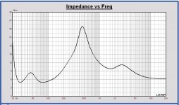
A possible reason of the resonance can also be the Leap basreflex model which has less damping. We can check that with by comparing the value of the impedance peaks. In attach the impedance of the Faital in the 70 L cabinet with the 161 cm2/24cm port. The peaks are both about 80 Ohm now.
In Leap the filling of port and cabinet can also be set.
It is best that I set the filling degree in Leap for the same impedance peak values as in your simulations.
Attachments
I have the MJK math sheets, but have not really used them yet, so it will take some time for me to figure it out. Have you tried making the port longer? Like maybe 33cm. Making it 132,4cm2 can also help.
Edit:
My idea of a good br type box is to push the resonant behaviour to a frequency where it is easier to deal with. I try to avoid stuffing the port, and use light stuffing to deal with reflections higher up instead, so they do not get excited.
Fluff can only get you so far, better use it where it counts.
Last edited:
I have the MJK math sheets, but have not really used them yet, so it will take some time for me to figure it out. Have you tried making the port longer? Like maybe 33cm. Making it 132,4cm2 can also help.
I also have the MJK math sheets. I did used them in the past for a TL design.
I didn't know that also basreflex was in it. I will have a look at it also.
The settings In Leap used for the damping were not good.
In the R. Small basreflex transfer there is a parameter QL, the Q-factor for the losses. In practice QL = 5 to 7 (cfr. Small).
My settings in Leap where conform a QL = 20.
I have increased damping in Leap and now the impedance peaks are around 50 Ohm instead of 80 Ohm.
With these settings the impedance dip with woofer filter becomes 3.5 Ohm instead of 3 Ohm.
Placing also a serial resistor of 0.6 Ohm in the woofer filter makes the dip 4 Ohm. Not good enough.
Making the cabinet volume larger to 80 L and tuning lower at 39 Hz (same port of 161 cm2 and 24 cm), gives a more damped basreflex system.
Using that one with the filter, the dip is 4.5 Ohm. That is 1 Ohm better than the actual system of 70 L.
Applying also a serial resistor of 0.6 Ohm in the filter, the dip becomes 5 Ohm.
With this cabinet volume of 80 L, tuned at 39 Hz, F3 = 52 Hz, F6 = 37 Hz and F10 = 30 Hz, sensitivity 91 dB full space (with serial resistor)
So, I think it is better to increase the cabinet volume to about 80 L and tuning at about 40 Hz to realize a more damped basreflex. Also better group delay.
It is possible with the current dimensions of the cabinet model I think.
Last edited:
A TL is a BR is a TL etc. etc... The lines can be blurry. Don't worry about the name.
Yes, the current model (The MonkeyBox) is quite good actually, that was why I just wanted to play with the port.
The problem I see is that the port is placed in a way that 1st reflections from the back of the driver can enter the port, and trigger unwanted modes inside the port at higher frequencies (over 200hz). It can be difficult to battle this after the sawdust has settled.
Almost sure that the impedance dip is related to the current basreflex impedance shape.
Indeed a resonance dip of the equivalent electrical parallel capacitance of the basreflex impedance and the inductance of the woofer filter.
Not sure I understand this. I see only one path for a low-frequency signal (about 30 Hz) to pass through the speaker, which is via the voice coil of the woofer. All other signal-to-GND connections in the x-over schematic are high impedance at this frequency. The impedance minimum of the whole thing therefore cannot be lower than the DC resistance of the voice coil. Am I missing something?
The impedance minimum of the whole thing therefore cannot be lower than the DC resistance of the voice coil.
Yes that is correct, the minimum impedance is caused by the compensating serial RLC, not by a resonance like I described. Dependent on the impedance shape and impedance value of the driver around the tuning frequency, the impedance inclusive filter becomes too low or not.
The compensation RLC cannot be omitted, otherwise there is too much SPL boost.
I think the best choice is a more damped basreflex, some serial resistance in the filter and a parallel compensation RLC and keep the minimum impedance above 5 Ohm. Like I mentioned in my previuos post #127
The SPL loss due to a serial resistance in the filter is no so much. The system becomes less damped with some low frequency SPL gain as a result. For higher frequencies the low pass filtering can be less to realize the same SPL.
Last edited:
I would prefer a more damped box design, but again, thats most likely just me, better to reduce the problem in one area rather than dealing with it in another.
Did you try making the port 132,4cm2 and 33cm long? The box volume is the same, really, actually slightly smaller since the port height is 4cm and not 4,8cm or 5cm. I am not so sure it is important with an RLC...?
Did you try making the port 132,4cm2 and 33cm long? The box volume is the same, really, actually slightly smaller since the port height is 4cm and not 4,8cm or 5cm. I am not so sure it is important with an RLC...?
I would prefer a more damped box design, but again, thats most likely just me, better to reduce the problem in one area rather than dealing with it in another.
Did you try making the port 132,4cm2 and 33cm long? The box volume is the same, really, actually slightly smaller since the port height is 4cm and not 4,8cm or 5cm. I am not so sure it is important with an RLC...?
You mean in a netto volume of 80 L for the woofer with that port. That volume is availble with the current cabinet dimensions.
The tuning frequency will be 31 Hz for a port of 132 cm2 and 33 cm.
In my simulation F3 = 62 Hz, F6 =39 Hz and F10 = 28 Hz.
For me that is ok, it is what I am proposing also for a higher minimum impedance. I will check with LR4 filter.
Is that ok for all of us ??
It most certainly has my vote!
Edit:
We will have to think of something to reduce reflections driver to port. Maybe a wide brace with felt?
Is a round tube not better for port reflections? One with a diameter of 12 cm for example. That is 113 cm2.
Tuning at 31 Hz with this Faital (or D.A.S.) the port area must be larger than 89 cm2 cfr. R. Small.
The impact of internal bracing, difficult to estimate it. That has to be measured in a prototype I think.
Yes that is correct, the minimum impedance is caused by the compensating serial RLC, not by a resonance like I described. Dependent on the impedance shape and impedance value of the driver around the tuning frequency, the impedance inclusive filter becomes too low or not.
The compensation RLC cannot be omitted, otherwise there is too much SPL boost.
I think the best choice is a more damped basreflex, some serial resistance in the filter and a parallel compensation RLC and keep the minimum impedance above 5 Ohm. Like I mentioned in my previuos post #127
The SPL loss due to a serial resistance in the filter is no so much. The system becomes less damped with some low frequency SPL gain as a result. For higher frequencies the low pass filtering can be less to realize the same SPL.
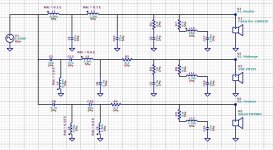
Hi Paul, are you referring to the LCR circuit in the bass section? Looking at the modelled impedance curve of the full speaker again I suspect that this LCR circuit compensates both bass reflex peaks in the impedance curve. This means the LCR has a rather wide bandwith, and it will not be high impedance at 30 Hz. The parallel combination of the LCR with the woofer may therefore result in the low impedance dip at 30 Hz.
I'd suggest to change the LCR such that it only compensates the upper bass reflex peak, and changing it to a much more narrow bandwidth in order to avoid any ill effects outside the upper bass reflex peak.
If the lower peaks also needs compensation (I don't expect it does), you could try a second LCR for that (just to see if that solves the issues we see in the simulation; we might still work out something easier for the final build).
It most certainly has my vote!
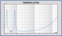
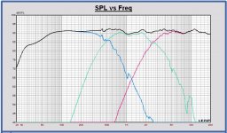
Here the SPL, impedance and schematic of the LR4 filter with the Faital Pro12PR320 in a 80 L netto volume and tuned at 31 Hz.
Minimum impedance is 5 Ohm without using a serial resistor in the filter.
F3 = 57 Hz, F6 = 42 Hz and F10 = 26 Hz, sensitivity 91 dB.
Maybe the tuning frequency has to be increased a little to improve F6, fB = 35 Hz for example. I will look at it later.
Attachments
It most certainly has my vote!
Edit:
We will have to think of something to reduce reflections driver to port. Maybe a wide brace with felt?
Which kind of reflections do you have in mind? reflections from the back wall emitting sound back towards the cone? Or standing waves between the top and bottom of the box?
My experience is that braces+felt are not as effective as one might think/hope/expect. In my experience, the best way to deal with internal waves/reflections is wool with long fibers to get as much drag as possible. Helmholtz absorbers might be useful, too.
Hi Paul, are you referring to the LCR circuit in the bass section? Looking at the modelled impedance curve of the full speaker again I suspect that this LCR circuit compensates both bass reflex peaks in the impedance curve. This means the LCR has a rather wide bandwith, and it will not be high impedance at 30 Hz. The parallel combination of the LCR with the woofer may therefore result in the low impedance dip at 30 Hz.
I'd suggest to change the LCR such that it only compensates the upper bass reflex peak, and changing it to a much more narrow bandwidth in order to avoid any ill effects outside the upper bass reflex peak.
If the lower peaks also needs compensation (I don't expect it does), you could try a second LCR for that (just to see if that solves the issues we see in the simulation; we might still work out something easier for the final build).
Yes it is about the LCR in the bass section.
To realize a smooth SPL response an LCR with this bandwidh is needed.
It is not possible with a smaller bandwith, then you get big ripple on the SPL, because the impedance is not flat anymore...
The lowest impedance peak is attenuated but not compensated.
The LCR is designed to compensate the highest impedance peak completely. It is optimized looking to the SPL mapping on the low frequency target.
The SPL is very sensitive to LCR value variation also. Again an argument to make the Q of the basreflex not too high.
Michael:
It was reflections that manage to get into the port.
I was thinking one could have a slanted brace that reflects some sound to the top of the enclosure, as well as some 3cm wool felt on strategic places.
But:
A round port could be used I guess, if you absolutely must, better make it 1 port, put it asymmetric to one side. A round port is not as resistive as a slot port.
Line all the corners with strips of wool dampening material, and have a slim column in the middle with fibreglass from bottom to top of enclosure. I do not see the point of lining the walls much, maybe except a few hot spots.
Last edited:
To realize a smooth SPL response an LCR with this bandwidh is needed.
It is not possible with a smaller bandwith, then you get big ripple on the SPL, because the impedance is not flat anymore...
The lowest impedance peak is attenuated but not compensated.
The LCR is designed to compensate the highest impedance peak completely. It is optimized looking to the SPL mapping on the low frequency target.
Hmmm. I'd expect it should be possible to compensate the upper bass-reflex peak without affecting the area below the peak too much. I will give it a try when I am back home.
- Home
- Loudspeakers
- Multi-Way
- Open Source Monkey Box