Drummer35
Why do you keep bringing back C4 into your schematics ?
Without a series resistor connected between C4 and ground, it doesn't qualify ( electrically ) as a bona-fide Zobel ( impedance equalizer ) which is the title of this thread.
I can see that you don't understand how a Zobel works.
( Functionally ), a lone capacitor across the driver load ( no resistor ) will only serve to destabilize the UHF output of your amplifier.
You've now been told a few times to keep the working impedance of your sims to 4 ohms ( or above ), so I don't understand your continuing reluctance to listen to this advice.
")
Why do you keep bringing back C4 into your schematics ?
Without a series resistor connected between C4 and ground, it doesn't qualify ( electrically ) as a bona-fide Zobel ( impedance equalizer ) which is the title of this thread.
I can see that you don't understand how a Zobel works.
( Functionally ), a lone capacitor across the driver load ( no resistor ) will only serve to destabilize the UHF output of your amplifier.
You've now been told a few times to keep the working impedance of your sims to 4 ohms ( or above ), so I don't understand your continuing reluctance to listen to this advice.
Earl
I learnt the lesson.
In fact, you, and other members, said at the first posts of this thread that using a parallel resistor should flatten impedance peaks, so no need for a zobel here.
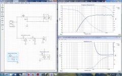
Attacked the screenshot with no zobel, so you see impedance is constant after xover point with the current config.
I put C4 directly to ground, to pad down the top end, but didn´t knew this practice could damage my amp, so thanks for your tip here.
Removed C4 since I dont want to hurt my amp.
Thanks!
I learnt the lesson.
In fact, you, and other members, said at the first posts of this thread that using a parallel resistor should flatten impedance peaks, so no need for a zobel here.
Attacked the screenshot with no zobel, so you see impedance is constant after xover point with the current config.
I put C4 directly to ground, to pad down the top end, but didn´t knew this practice could damage my amp, so thanks for your tip here.
Removed C4 since I dont want to hurt my amp.
Thanks!
Attachments
Last edited:
Earl
<<<<SNIP>>>>
I put C4 directly to ground, to pad down the top end, but didn´t knew this practice could damage my amp, so thanks for your tip here.
Removed C4 since I dont want to hurt my amp.
Thanks!
To reduce top-end ( anywhere in a circuit ) the normal practice is to use a series inductor/coil.
- Circuit impedance will typically start to rise above the coil's Fc point ( this is generally considered to be more desirable/safer than lowering the impedance ) .
One can parallel a resistor ( even a variable resistor ) to tailor how much attenuation ( out of a maximum 6db per octave ) one obtains.
It can be done, it's just the way you did it.I put C4 directly to ground, to pad down the top end,
Impedance compensation for dome tweeters is usually done at resonance with a series RLC in parallel with the driver. The top end doesn't usually need to be compensated. Amplifiers are usually treated just outside their feedback loop so you should be able to leave it alone.
It can be done, it's just the way you did it.
Impedance compensation for dome tweeters is usually done at resonance with a series RLC in parallel with the driver. The top end doesn't usually need to be compensated. Amplifiers are usually treated just outside their feedback loop so you should be able to leave it alone.
I think I got it.
Not necessary the RLC this time. I get good impedance graphs for both the cd and the woofers.
Just will order several resistor values to play with the voltage divider, to pad down the cd. Forgot the wrong cap idea...
Thanks for your advices!
Hey Drummer,
Wait a sec. Do you have actual measurements for the mid-woofer? Also, once your driver is in a horn things will change unless you use what the manufacturer did for the measurements.
Now that you have learned how FR/ impedance and filters interplay, your next step is to evaluate your 2-way. This is a back of the envelope thing, just to make sure the drivers will play nice. THEN measure in cabinet, simulate, and finally buy stuff.
I use OmniMic which is expensive but damn, does everything well and quickly. Room EQ Wizard is another good option and there are tweaks to let you use it for Z measurements. Still needs a calibrated mic.
Best,
E
Erik,
I have not measured the woofers.
At the moment Im using winisd for the box simulation.
Will make a prototype with an internal movable panel so I can try different alignments and choose what works better.
Then I should take your advice and measure the response to make the filter according with.
One more question regarding xsim,
Im a bit worried about phase delay and group delay and dont know how accurate are those graphs.
I mean, I try to keep group delay down, but dont know if Im loosing my time. Will the speaker box affect drivers phase too?
Thanks for your help.
Last edited:
The box type will affect group delay a great deal, but that's got more to do with the type (sealed, ported, horn, etc.) than with any particular size/port, etc.
What matters most is proper phase alignment across drivers. That is, that the woofer/tweeter phase alignes, giving a deep and wide null when one is inverted.
What is then quite debatable is the effect that sealed vs. ported, etc have on bass quality as opposed to frequency response.
You may also want to investigate Harsch crossovers, but that may seem too advanced! I think there's a recently revived thread. They don't align quite the same way, and have some interesting potential benefits.
Also, you'll realize that baffle step and trading bass extension for efficiency will be important choices you'll need to make. This will affect the necessary horn padding.
Best,
E
What matters most is proper phase alignment across drivers. That is, that the woofer/tweeter phase alignes, giving a deep and wide null when one is inverted.
What is then quite debatable is the effect that sealed vs. ported, etc have on bass quality as opposed to frequency response.
You may also want to investigate Harsch crossovers, but that may seem too advanced!
I think there's a recently revived thread. They don't align quite the same way, and have some interesting potential benefits. Also, you'll realize that baffle step and trading bass extension for efficiency will be important choices you'll need to make. This will affect the necessary horn padding.
Best,
E
Erik, do you have any evidence that this is always the best option?that the woofer/tweeter phase alignes, giving a deep and wide null when one is inverted.
- Status
- This old topic is closed. If you want to reopen this topic, contact a moderator using the "Report Post" button.
- Home
- Loudspeakers
- Multi-Way
- comp driver zobel help!