I want to redesign my midrange chamber for my Scanspeak 10F. Unfortunately I can't find many resources on midrange chamber design. I used to have a 4.5'' x 4.5'' x 4'' heavily stuffed chamber for my 10F, but I know from physics this being a near cube shape isn't optimal for standing waves.
What about a cylindrical chamber made from PVC pipes?
What about a cylindrical chamber made from PVC pipes?
I want to redesign my midrange chamber for my Scanspeak 10F. Unfortunately I can't find many resources on midrange chamber design. I used to have a 4.5'' x 4.5'' x 4'' heavily stuffed chamber for my 10F, but I know from physics this being a near cube shape isn't optimal for standing waves.
What about a cylindrical chamber made from PVC pipes?
They can work GREAT, but only IF:
You keep the diameter close to the same dimension as the length.
The end of the pipe which is opposite the driver is NOT a flat surface.
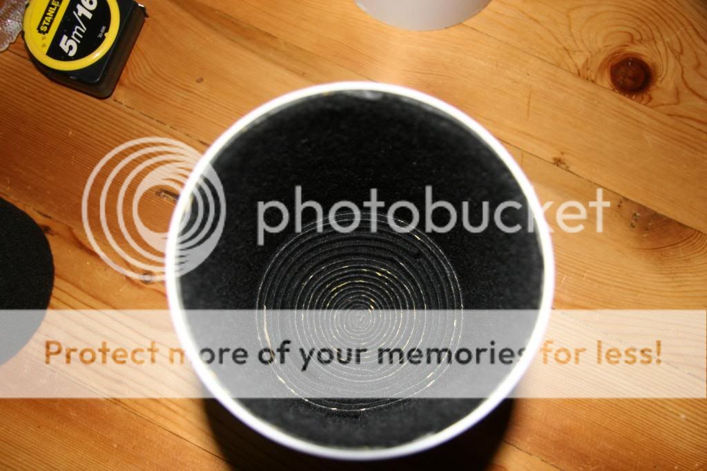
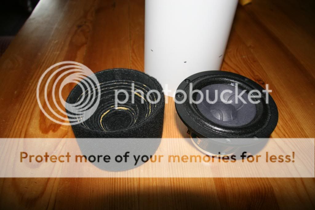
Line the circumference with felt, and also fill the chamber with acoustic.
They can work GREAT, but only IF:
You keep the diameter close to the same dimension as the length.
Really? If I use a 4'' diameter pipe the optimal length of the pipe would be 4''? That's perfect for my build then.
The end of the pipe which is opposite the driver is NOT a flat surface.
What would you do to get a non flat surface end of the pipe? I've only seen flat surface caps for the pipes.
Triangular Peramid [1]
back-box geometry yields a wider spread of standing wave modes (SWMs) than that of a cylinder or a parallelepiped. Use layers of felt padding to line the internal walls and pack the apex to mitigate the reduced SWM and back wave levels that remain.
Regards,
WHG
Reference [1]
Triangular Pyramid -- from Wolfram MathWorld
I want to redesign my midrange chamber for my Scanspeak 10F. Unfortunately I can't find many resources on midrange chamber design. I used to have a 4.5'' x 4.5'' x 4'' heavily stuffed chamber for my 10F, but I know from physics this being a near cube shape isn't optimal for standing waves.
What about a cylindrical chamber made from PVC pipes?
back-box geometry yields a wider spread of standing wave modes (SWMs) than that of a cylinder or a parallelepiped. Use layers of felt padding to line the internal walls and pack the apex to mitigate the reduced SWM and back wave levels that remain.
Regards,
WHG
Reference [1]
Triangular Pyramid -- from Wolfram MathWorld
Last edited:
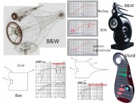
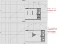
B&W and Vivid engineers use a stuffed tapered-tube behind mids and tweets box to reduce enclosure resonances without extensive stuffing and bracing-reflections. An exponential taper is often used for good performance with modest length. This sealed air volume is more linear than the compliance on most speakers. Also works for larger diameter(10"-12") midbass which are pushed to higher frequencies for horns/AMT blending.
An open volume (B&W uses an exposed sphere for low edge diffraction) around the driver to avoid early reflections, followed by a well stuffed rear tapered tube is documented at B&W and Vivid.
An open volume (B&W uses an exposed sphere for low edge diffraction) around the driver to avoid early reflections, followed by a well stuffed rear tapered tube is documented at B&W and Vivid.
Attachments
I did R&L up firing subs with 12" PEERLESS sub drivers n' radiators, the walls were made of concrete, fibre reinforced, with pva glue mixed in for ultimate strength. I used 2 sono-tubes one inside the other as a form for the concrete. Did it up as yours & they rang like a bells. Used heavy sound proofing (tar roll paper type) on the inside...better but had to put it on the outside as well with all the stuffing inside they sounded great, heavy though around 400lbs each ")
What is the lowest resonant frequency of your square box? And if you have heavily stuffed the box how strong is the sound going to be in the box at this frequency? Can you see anything around this frequency in your measurements?I want to redesign my midrange chamber for my Scanspeak 10F. Unfortunately I can't find many resources on midrange chamber design. I used to have a 4.5'' x 4.5'' x 4'' heavily stuffed chamber for my 10F, but I know from physics this being a near cube shape isn't optimal for standing waves.
Why close the rear chamber?
Would a well stuffed, maybe even over stuffed, open tube be a suitable loading for a mid frequency driver?
Leaving it open can work quite well, but I can also see where, in some cases, a closed chamber would offer better performance. Like many things in audio, the answer is, "it just depends".
p.s. I use a well stuffed, open ended cardboard tube, in my own system.
But, then again, in my case I am housing a cone driver that is front loaded by a very large horn, and I wished for the driver's impedance to be as flat as possible and not raised much from it's free air resonance. This could work for other mounting techniques as well, provided the front-to-back distance is large enough as to avoid lower frequency cancellation.
Looks interesting - what's the product and how did you form it?
Thanks...
Thanks...
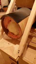
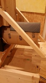
This is what I did a few years back. Worked great and I did a lot of experimenting!
xrk used an interesting "dagger" design in his fast reference.
http://www.diyaudio.com/forums/full-range/273524-10f-8424-rs225-8-fast-ref-monitor.html
http://www.diyaudio.com/forums/full-range/273524-10f-8424-rs225-8-fast-ref-monitor.html
What post number?xrk used an interesting "dagger" design in his fast reference.
http://www.diyaudio.com/forums/full-range/273524-10f-8424-rs225-8-fast-ref-monitor.html
Why close the rear chamber?
Would a well stuffed, maybe even over stuffed, open tube be a suitable loading for a mid frequency driver?
We have had great success with midTLs for such an application. Usually a heavily tapered line running out the back and stuffed until aperiodic.
http://www.diyaudio.com/forums/full-range/144099-thread-tysen-variations-fast.html
dave
Why close the rear chamber?
Would a well stuffed, maybe even over stuffed, open tube be a suitable loading for a mid frequency driver?
Works for me
Attachments
Looks interesting - what's the product and how did you form it?
Thanks...
A comically inexpensive version of that could be made from a couple rolls of cork bicycle tape. Probably pretty effective, too.
What post number?
1st post, scroll down through the pics, it's the fourth one, internal shot.
Here's xrk talking about it, 3rd post.
http://www.diyaudio.com/forums/multi-way/287609-what-do-you-put-sealed-midrange-enclosure.html
- Status
- This old topic is closed. If you want to reopen this topic, contact a moderator using the "Report Post" button.
- Home
- Loudspeakers
- Multi-Way
- Help with midrange chamber design