I thought of that too but then ultimately you have the impedance of the driver. Neither driver goes to 1ohm at HF. Or it is parallel of both drivers but that should be not worse than 4ohms?
But HF choose lowest impedance route and C1/C3 sits closest to amp and is far lower impedance route than route out thru drivers.
That said i did read your schematic wrong in that thought S1 driver was tweeter because personal draw tweeters visual on top over woofers, and that make a difference and is mistake by me, sorry : )
So by mistake thought it was a tweeter high pass route trying to have a second order electric filter, but it was a woofer route and calls for a low pass function instead. Therefor culprit as written in previous post is not C3 but C1, in XSim right click C1 and choose "Open" circuit or just pull C1 out of circuit to a empty place without wire connection and your impedance plot will change significantly in real time.
You probably have C1 there for some EQ correction and if important to keep it try add some x,xx R value in electric series, or a x,xx value inductor that hinders HF can pass the route. One can sweep the values up and down in XSim and see plot changes in real time and think this is very handy.
Attachments

Last edited:
Hi X,
Late to the party.
Concerning their sound qualities, how do you compare this TL with MLTL, closed-end TL (Nautilus), and various types of tapped (loading both sides of driver) ?
You are one of the very few who built them all !

Good question. I don't have them all side by side so have to go from memory and a quick side by side with same song but different dirvers. I have a tapered (under-damped) TL with a FF105WK on my left desktop speaker and a ML-TQWT Karlsonator with CHN-70 on the right side. I can slide the balance left and right and compare. Over on the stand mounts, I have a Dagger (sort of like short Nautaloss TL) 10F/RS225 FAST on the right side and the new DC28F/DC130A TL (critically-damped?) TL on the left side. I can mix a song into mono so that the same content plays on both sides and have a listen. Then I have folded wall mount ML-TL with the A7.3 all by iteself.
So I will try to avoid characterizing the MF-HF voicing because that is driver dependent and instead talk about the bass and upper bass that the TL provides.
The under-damped tapered TL sounds less full but more analytical and precise than the Karlsonator, even though they both measure down to 60Hz as the bass corner frequency. The Karlsonator ML-TQWT sounds bigger, richer, full-bodied and very musical. but less analytic, more reverberant.
Now moving over to the stand mount monitors, both are flat within +/-2dB over 50Hz to 16kHz, with the DC28F/DC130 reaching a solid 20kHz and above. Listening to both playing in pseudo stereo - they are amazingly balanced. This is surprising because the little TL is only a 5.25in driver vs the 8in RS225 on the other side. The 8in is however, a sealed Linkwitz transform alignment for the bass. Now panning left and right, they still both sound about the same except for the higher HF reach of the DC28F - I can hear the "air" of instruments more. The mids (vocals) of the 10F/8424 are very clear and very low HD, the DC130A is quite nice but discernable that it is edged out by the 10F, but not by much at 82dB SPL listening levels.
So I think the clear finding (as confirmed by measurement) is that the DC130A damped TL sounds a lot like a bigger sealed LT woofer. Both have about the same GD and transient dynamics are similar. But, but... upon careful listening to a stand-up bass stroked with a bow, the bass extension on the TL is deeper with a shallower fall-off.
The test track is Norah Jones "Broken" played on continuous loop via Audacity.
https://www.youtube.com/watch?v=ZEk6vEQBuns
So surprisingly, the $40 little TL is giving the bigger $162 10F/RS225 a run for the money. Very interesting result actually
So of all of these, which do I like best for this particular song?
For musicality and listening, the Karlsonator wins. For accuracy as a monitor - the little DC130A TL and RS225 sealed tie, but the nod goes to the TL for deeper bass extension. Now imagine a TL using a RS225P - that might be very cool.
How does this compare to an OB KaZba? Very different - OB slot loaded is very present and immediate, but bass is not as deep in extension.
Last edited:
But HF choose lowest impedance route and C1/C3 sits closest to amp and is far lower impedance route than route out thru drivers.
That said i did read your schematic wrong in that thought S1 driver was tweeter because personal draw tweeters visual on top over woofers, and that make a difference and is mistake by me, sorry : )
So by mistake thought it was a tweeter high pass route trying to have a second order electric filter, but it was a woofer route and calls for a low pass function instead. Therefor culprit as written in previous post is not C3 but C1, in XSim right click C1 and choose "Open" circuit or just pull C1 out of circuit to a empty place without wire connection and your impedance plot will change significantly in real time.
You probably have C1 there for some EQ correction and if important to keep it try add some x,xx R value in electric series, or a x,xx value inductor that hinders HF can pass the route. One can sweep the values up and down in XSim and see plot changes in real time and think this is very handy.
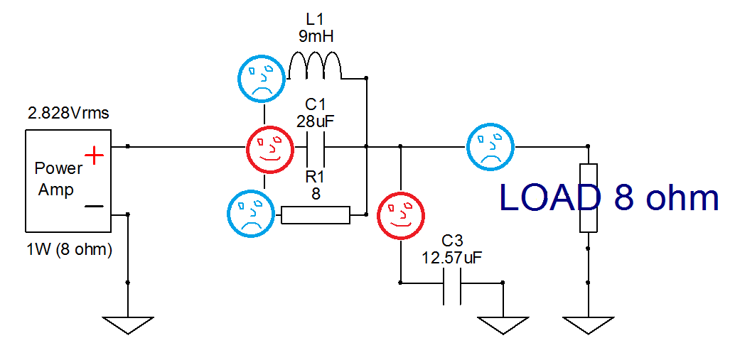
Ok thanks - I see the happy face short to ground = ESR of caps then...
:Now imagine a TL using a RS225P - that might be very cool.
The RS180P-4 also .. Shame I can't get this in Europe
Sent from my iPhone using Tapatalk
Bill poster, both woofers seems in stock at our EU neighbors : )
RS180P-4 Dayton Audio RS180P-4 7tum
RS225-8 https://www.intertechnik.com/Shop/L...yton-Low-midrange/_RS225-8_1768,en,7058,52679
RS180P-4 Dayton Audio RS180P-4 7tum
RS225-8 https://www.intertechnik.com/Shop/L...yton-Low-midrange/_RS225-8_1768,en,7058,52679
Xrk approx how far down the line is the driver? Looks about one fifth - I've seen some recent TL builds putting the driver approx one quarter down so wondering what these different approaches mean
Sent from my iPhone using Tapatalk
The plan shows 7in down a 48in line or about 15%. It really is something that needs to be optimized and values between 15% to 33% can all work. For this one, it was a practical consideration to provide clearance for the tweeter and to provide some sort of stub to help cancel the fundamental reflection null from the vent terminus.
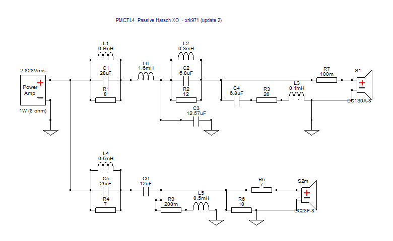
Passive XO update
I was having a real hard time translating the component values from PCD into a generic electrical schematic diagram. I was still missing the key inductor to make the woofer a 4th order low pass (a big 1.6mH unit). Once that was added and I found that Xsim has the opposite sense for time delay (positive value for setback is negative delay), everything seems to look good and matches what PCD has. So no more virtual shorts to ground via cap ESR anymore.
Here is rev2 circuit schematic:
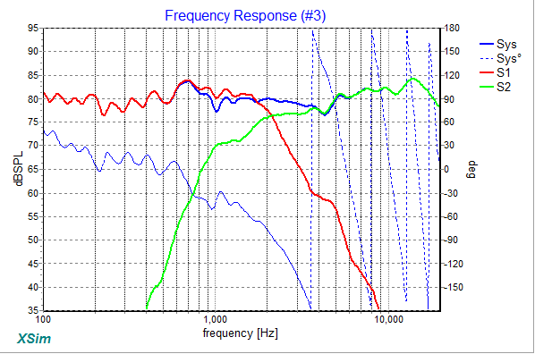
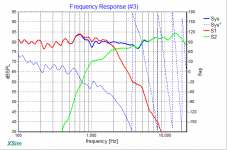
Here is predicted SPL and XO response in Xsim:
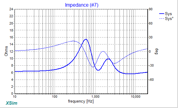
Here is Impedence in Xsim:
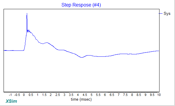
Here is SR from Xsim:
It is a complicated circuit to be sure, and my next step will be to go in and slowly remove blocks to simplify to the extent possible and accept a more ragged frequency response. This is where spending more money a driver that is natively smooth helps because you don't need to mess with notch filters which aren't cheap. So perhaps a passive version could use an AC130F1 (which is as smooth as a midbass driver can get). Also, more attention paid to smooth rebates, and even a trapezoid baffle can remove the ripples even farther. In short, an active miniDSP version allows use of lower cost drivers and simpler cabinets which are then compensated by DSP. With an all speaker level passive approach, you want to spend more money on smooth drivers, smooth baffles, smooth lips/edges to avoid diffraction wherever possible. In the end, a passive line level speaker will cost more to achieve the same level of flat SPL and transient perfect that an active DSP can do for essentially no extra cost.
I was having a real hard time translating the component values from PCD into a generic electrical schematic diagram. I was still missing the key inductor to make the woofer a 4th order low pass (a big 1.6mH unit). Once that was added and I found that Xsim has the opposite sense for time delay (positive value for setback is negative delay), everything seems to look good and matches what PCD has. So no more virtual shorts to ground via cap ESR anymore.
Here is rev2 circuit schematic:
Here is predicted SPL and XO response in Xsim:
Here is Impedence in Xsim:
Here is SR from Xsim:
It is a complicated circuit to be sure, and my next step will be to go in and slowly remove blocks to simplify to the extent possible and accept a more ragged frequency response. This is where spending more money a driver that is natively smooth helps because you don't need to mess with notch filters which aren't cheap. So perhaps a passive version could use an AC130F1 (which is as smooth as a midbass driver can get). Also, more attention paid to smooth rebates, and even a trapezoid baffle can remove the ripples even farther. In short, an active miniDSP version allows use of lower cost drivers and simpler cabinets which are then compensated by DSP. With an all speaker level passive approach, you want to spend more money on smooth drivers, smooth baffles, smooth lips/edges to avoid diffraction wherever possible. In the end, a passive line level speaker will cost more to achieve the same level of flat SPL and transient perfect that an active DSP can do for essentially no extra cost.
Attachments


Plan for front firing TL
I just realized I never posted the plan for the TL as-built with the front firing vent. This plan is literally drawn on the back of an envelope.
Internal width is 6.0 inches. External dimensions shown are for thinwall 0.1875in foam core. Just maintain internal dimensions approximately at 5in, 4in, 3in, 1.5in deep for each leg. Each leg length is 12in. Driver is 7in from closed end.
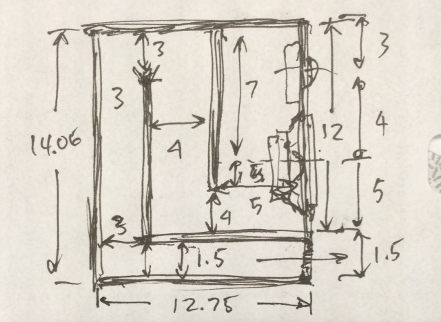
Attachments

This is the type of TL line I had in mind, excuse the simple sketch. Line length just over a meter, around 105-110cm to tune the line to around 60-65hz (for the Faital). The relatively high fs makes it fairly easy.
110cm is closer to 77Hz. You should follow my sketch and reduce dimension of the internal width to 5.5in - as that has been modeled for the 5FE120 and will probably be accurate. Your line will probably work fine, but a bit short to reach 60Hz.
Just take the inverse of the line length in meters and multiply by speed of sound at 342m/sec and you get frequency for 1-wavelength, now divide by 4 for 1/4-wave TL. A tapered (narrowing) line will extend a little lower than based on this and an expanding TL a little but higher in frequency.
342/(1.1 x 4) = 77Hz
342/(1.1 x 4) = 77Hz
- Home
- Loudspeakers
- Multi-Way
- Low-Cost PMC-inspired TL Monitor with DC130A and DC28F