Nearly all dipole speakers use either a flat baffle, U-frame, or H-frame. All these baffle types have in common a sharp termination separating the front and back sound waves. What is it about dipoles that eliminates the edge diffraction, or does it exist and people simply ignore it?
Roundovers are common and highly recommended for monopoles, but when it comes to dipoles, no one bats an eye at thin sharp edges. Do the opposing waves really totally cancel out the edge diffraction? Probably not, because we know that the shape of the baffle affects (at least) the response around and above the dipole peak.
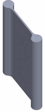
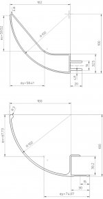
Anyway, I've attached a quick sketch of what an ideal dipole baffle edge might look like. It has 75 mm radii all around. Waste of time, or worth further study?
Roundovers are common and highly recommended for monopoles, but when it comes to dipoles, no one bats an eye at thin sharp edges. Do the opposing waves really totally cancel out the edge diffraction? Probably not, because we know that the shape of the baffle affects (at least) the response around and above the dipole peak.
Anyway, I've attached a quick sketch of what an ideal dipole baffle edge might look like. It has 75 mm radii all around. Waste of time, or worth further study?
Attachments
The diffraction is there, just like with a conventional box. Additionally, you get the radiation from the back that diffracts around the edge, coincident with the diffraction of the front-wave. The result is a more pronounced effect on the amplitude-response.
It helps to use a minimum size baffle. When the source is not significantly smaller than the baffle, the diffraction gets smeared in time. The result is a smoothing of the impulse response and amplitude response.
It helps to use a minimum size baffle. When the source is not significantly smaller than the baffle, the diffraction gets smeared in time. The result is a smoothing of the impulse response and amplitude response.
Hi,
an alternative idea to the symmetrical layout may be one that has a bowed backwards shape, using aluminum profiles as shown in the pics.
Instead of the ESL-panel in the 3rd pic any flat baffle can be used.
The slots make mounting of a baffle very easy ... 4screws suffice to mount a whole system.
I´m not sure if the profiles are still available commercially.
I found them years ago at a company that builds Truck-Trailers.
So take it just as another idea 😉
jauu
Calvin
Attachments

I think it would be worthwhile for the reasons keyser mentioned, but there's a trade-off. To me the main advantage of a dipole is the wide bandwidth constant directivity that you can get with a narrow baffle or baffle-less dipole. Adding 75mm+ per side will add significant width to the baffle. With my current cardioid project I noticed a smoother response with 3" radius round overs vs sharp corners.
I wonder if the wings shown above would create a cavity resonance in the operating band of the panel, much like a typical u-frame one might use for lower frequencies.
I wonder if the wings shown above would create a cavity resonance in the operating band of the panel, much like a typical u-frame one might use for lower frequencies.
Anyway, I've attached a quick sketch of what an ideal dipole baffle edge might look like. It has 75 mm radii all around. Waste of time, or worth further study?
Hi,
Yes, but where is located driver on this baffle ?
In OB, front wave and rear wave are very different, at rear generally it's only midrange. I say this for mid/hight frequencies, beyond near 200 hz..
Maybe first, predict response curve by locate driver on baffle, you can use :
Home of the Edge
but this assumes that front and rear wave are the same..
Phil.
I've noticed on The Edge that defining the system as a dipole essentially doubles all the diffraction wiggles. I assume that is correct for thin and simple baffles. The front side reflections from the edge are out of phase with the front driver face and the back side diffraction is in phase with the back side ( so out of phase with the front).
The sketch with the first post, in spite of the smooth radii, is still a forward projection and will cause some reflections. The one by Calvin looks much more appropriate.
Regards,
David
The sketch with the first post, in spite of the smooth radii, is still a forward projection and will cause some reflections. The one by Calvin looks much more appropriate.
Regards,
David
Those look great for the front wave but seems to make things even worse off for the rear wave. Can the rear diffraction be safely ignored, i.e. it is an insignificant part of the indirect sound?I've noticed on The Edge that defining the system as a dipole essentially doubles all the diffraction wiggles. I assume that is correct for thin and simple baffles. The front side reflections from the edge are out of phase with the front driver face and the back side diffraction is in phase with the back side ( so out of phase with the front).
The sketch with the first post, in spite of the smooth radii, is still a forward projection and will cause some reflections. The one by Calvin looks much more appropriate.
Regards,
David
When a dipole operates in it's dipole range below dipole null, edge termination doesn't mean a thing. Baffle width and partially driver diameter determine that, baffle/edge thickness or wings increases the pathlength ie. shifts dipole null lower.
Just above the dipole null strong wave interferences override edge shape effect, it takes over many combing cycles later.
As mentioned above, Edge simulation is nice way to study these. Obviously Edge is based on pistonic driver and minimally thin baffle (thickness/wing effect should be added to baffle width)
In real life it is almost impossible to get dipole null above 6kHz. That is why we see funny baffle shapes in LX521 and NaO - to minimize edge diffractions.
Last edited:
Hi 454Casull
I have done something similar to my midrange.
http://www.diyaudio.com/forums/multi-way/123512-ultimate-ob-gallery-145.html#post4153719
My main idea was to extend the LF response like a H-baffle as well as minimising edge diffraction (similar to no baffle) and the fact that they are foam helps too. As with any H-baffle there will be a 1/4 wave notch at 340/(.075x4)= 1.1kHz.
DIY is all about experimenting so give it a go, you can build a simple flat baffle and then add the rounds with a carpet tube or carved polystyrene.
My next iteration of my design will extend this approach to my woofers but with a toroidal baffle with a elliptical instead of round edges.
Cheers
Tim
This seems strange to me : the diffraction is generally modelled as a secondary source that is in phase opposition to the incident field toward the front face.I've noticed on The Edge that defining the system as a dipole essentially doubles all the diffraction wiggles. I assume that is correct for thin and simple baffles.
So if the setup (back/front geometry and radiation) is symetrical, and if the edge is thin, diffraction due to the back wave is in phase opposition to diffraction due to front wave and both should cancel in any direction.
Bipole radiation will cancel because the front and rear response at the baffle edge are out-of-phase, but dipole does essentially double the diffraction response on-axis. The off-axis changes with angle.This seems strange to me : the diffraction is generally modelled as a secondary source that is in phase opposition to the incident field toward the front face.
So if the setup (back/front geometry and radiation) is symetrical, and if the edge is thin, diffraction due to the back wave is in phase opposition to diffraction due to front wave and both should cancel in any direction.
John K provided a very good dipole spreadsheet that also takes driver T/S parameters into account. His site is probably one of the best for coverage of dipole theory.
dlr
Hi,
I still have difficulty to understand dipole theory when acting as front wave is equal to rear wave..
In the real life, we can observe that is not true.
Locate a driver on OB, mesure front and rear at same distance, and note they are very different.
Phil.
I still have difficulty to understand dipole theory when acting as front wave is equal to rear wave..
In the real life, we can observe that is not true.
Locate a driver on OB, mesure front and rear at same distance, and note they are very different.
Phil.
Thanks for the link to John K's dipole spreadsheet but in the help file DIPOLE DESIGN.CHM, he says :Bipole radiation will cancel because the front and rear response at the baffle edge are out-of-phase, but dipole does essentially double the diffraction response on-axis.
If the front and rear radiated signals are identical in amplitude but 180 degrees out of phase, i.e. anti-symmetric, as they would be for ideal, front and rear point sources, and if the edge treatment is identical, then the front and rear diffraction signals will also be identical but out of phase like the direct signals
That is exactly what I said in my post above. So if both signals are identical but out of phase at the edge, those signals will simply cancel and for ideal dipoles, there will be no diffraction signal.
In real world, it is a bit different : front and back radiation are not equal and pathes are not equal.
In real world, it is a bit different : front and back radiation are not equal and pathes are not equal.
Yes, except using two same drivers, back to back mounting, wiring in parallel and out of phase.
Just one problem, the distance between the two drivers..
Phil.
The issue is, I think, reference or perspective. First, let's stipulate that we are speaking of an ideal case, a point source dipole with equal front and rear radiation with a non-zero separation (a separating baffle). We also have to stipulate a point source mic. With regard to the diffraction signal, the separation and any mic location has a significant change in the response since even for a monopole the diffraction signal changes with mic position that further complicates it. However, for an ideal point source dipole (or bipole), the interaction at the baffle edge should make that issue moot.Thanks for the link to John K's dipole spreadsheet but in the help file DIPOLE DESIGN.CHM, he says :
If the front and rear radiated signals are identical in amplitude but 180 degrees out of phase, i.e. anti-symmetric, as they would be for ideal, front and rear point sources, and if the edge treatment is identical, then the front and rear diffraction signals will also be identical but out of phase like the direct signals
For a single driver (dipole), from the standpoint of a mic placed facing the front of the driver, the front wave is in-phase (call it positive). The rear wave, from the standpoint of a mic placed facing the rear of the driver, is out-of-phase (call it negative). But from the perspective of a mic at the baffle edge, the rear wave is also in-phase because the wave is propagating in the same direction as the front wave at the edge. The issue is perspective of rear wave to front wave at the edge. Let's consider the wave from the front to be the reference.
For a dipole, at the baffle edge, the front wave propagation is "positive" (so-to-speak) while the rear wave propagation is also "positive" from the perspective of the front wave. They are traveling in the same direction relative to each other.
The above is true for direct waves as well as for diffracted waves.
A bipole (requiring two separate drivers) are the converse. The waves from each driver are "launched" at the same time, reach the baffle edge at the same time, and and are propagating in a way that they are out-of-phase with each other from the perspective of our reference, the front wave. For a mic placed in front of either driver, an ideal bipole would act as an infinite baffle. The waves would cancel completely at all places on the plane of the baffle.
Relative to each other, the dipole waves from the perspective of the front wave, are in-phase at the baffle edge. The case in which the ideal would be total cancellation is the bipole, two drivers connected with the same polarity, not the dipole. The paths to the baffle edge are identical. Cancellation occurs with the bipole, reinforcement occurs with the dipole, from the perspective of the front wave at the baffle edge. When you place the reference to be a mic at a single point anywhere other than the baffle edge, it gets more complicated without considering non-symmetric waves.That is exactly what I said in my post above. So if both signals are identical but out of phase at the edge, those signals will simply cancel and for ideal dipoles, there will be no diffraction signal.
In real world, it is a bit different : front and back radiation are not equal and pathes are not equal.
Dave
I tried to add this p.s., but was cut off due to time.
p.s. The issue remains perspective and what we are considering. For a dipole, the pressure on the plane of the baffle itself for a dipole is zero, but the volume velocity is not. This may be where I am looking at it differently. The pressure is zero at the baffle edge for a dipole, but that's because the volume velocity due to each driver is equal and in the same direction at the edge. I think that I have been thinking volume velocity vs. pressure.
A mic facing the front of the driver will see double the volume velocity as well (before time delays due to separation), but will also see a doubling of the pressure at that point before taking separation into account. The pressure will be zero on the plane of the baffle, but only on that plane. So I guess that my perspective has been on the volume velocity. At very low frequency, there is very high volume velocity, but almost no pressure. So looked at that way, it is total cancellation. The overriding factor is separation distance.
So I think that my consideration was different due to perspective. Pressure at the baffle edge (and on the baffle plane) does "cancel" because volume velocity is out-of-phase, but that volume velocity is double that from a single driver. However, this is limited only to the baffle edge itself. Away from the baffle edge, the unequal distance from the dipole point sources results in different time delays and also different pressure due to distance, so again, taking the baffle edge pressure only doesn't fully describe the situation. Considering only the pressure at the edge, without considering velocity, doesn't describe what is occurring where we are truly concerned, the response at a single point in front of the driver. A pressure mic alone at the baffle edge might lead one to believe that there was no pressure wave on either side of the baffle. In that sense, yes, there is cancellation, but only from the perspective of points along the baffle edge.
Dave
Last edited:
Thanks DLR for all those infos but, well, on the John K. Dipoles and Diffraction, I found a further explanation, which I do agree with :
Comparing this result to the result for a conventional speaker given above we see that the differences is the factor of 2 multiplying the second term. This suggests that diffraction for a dipole is twice that of a conventional speaker with peaks of +6dB and nulls appearing in the response above the initial dipole peak. But since the diffraction sources cancel, is this really diffraction or simply the sum of the front and rear response? That is really a matter of how one chooses to interpret the result.
This also means that the results given by The Edge software are false for dipole diffraction (but should be right for bipole !).
This also means that the results given by The Edge software are false for dipole diffraction (but should be right for bipole !).
Not sure, and Edge don't work with bipole..
Bipole means 2 (or more) drivers in phase.
A Guide to Bipolar, Dipolar, & Direct-Radiating Monopole Surround Speakers (PART I) - Blu-ray Forum
Phil.
Have you French guys read these? More mathematics, goes over my head but the principle is there!
http://www.mellowacoustics.com/articles/Disk_in_a_circular_baffle.pdf
http://www.dipolplus.de/thema4.html
My measurements show that nullification is at 80-85¤ of a conical driver. The unsymmetry of front and back radiation does only little harm to dipole function, mainly just smoothing the dipole null. I have a planar Neo8 driver as mid now, and it performs pretty close to theory/Edge.
In real life, also the driver's frame, spider, magnet and nearness of other drivers and frame structures etc. obstructions an unsymmetries disturb dipolity, mostly in vertical plane. I believe that all these problems can't be calculated and estimated - build a proto and measure!
Last edited:
With regard to the phase of front and rear components, I think it works like this: starting with a positive pulse from the front of the speaker that + pulse runs off to the edges and most of the energy radiates out and also bends around the edge. Some of it also reflects from the edge forwards and that reflected part is out of phase. Note that the energy that went around the corner is still positive in phase, only the edge reflection had its phase reversed.
At the same time the negative pulse from the back side runs off to the same edges (but other side). Some of that energy bends around to the front side and stays in its original negative phase. Some energy from that back phase also bounces off the edge and reverses phase (to positive) but we don't care about it, only the component diffracting around to the front matters.
So the edge energies (front reflection and rear diffraction) are both negative relative to the front driver response.
David
- Status
- Not open for further replies.
- Home
- Loudspeakers
- Multi-Way
- Baffle edge diffraction with dipole radiation