About dipole radiation characteristics,
Dipoles and Open Baffles
A cardioid is a little different animal in theory, but very very tricky to do "right" in real world. It is always worth to measure off-axis 0-180¤. A problem in measurements is that when output is low (lateral nulling), the program might pick the loudest signal from a room reflection --> go outdoors!
The challenge in dipoles and cardioids is, that they show this pattern only in the lower end and with diminishing efficiency towards low frequencies. Usable (ie. constant directivity pattern) range is typically 2-3 octaves per unit
https://www.kirchner-elektronik.de/upload/15522394-DIPOL-CARDIOIDeng.pdf
Dipoles and Open Baffles
An externally hosted image should be here but it was not working when we last tested it.
A cardioid is a little different animal in theory, but very very tricky to do "right" in real world. It is always worth to measure off-axis 0-180¤. A problem in measurements is that when output is low (lateral nulling), the program might pick the loudest signal from a room reflection --> go outdoors!
The challenge in dipoles and cardioids is, that they show this pattern only in the lower end and with diminishing efficiency towards low frequencies. Usable (ie. constant directivity pattern) range is typically 2-3 octaves per unit
https://www.kirchner-elektronik.de/upload/15522394-DIPOL-CARDIOIDeng.pdf
Last edited:
I don't think the harsness in the midrange that i hear is related to the power response, which approximates cardioid. Putting a notch @ 750Hz improved the sound quality, so i think im hearing the cone break up mode of the 10inch midbass which also appears in the burst decay.
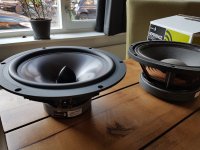
Before anything else, i will try the newly bought Dayton rs270 woofers") .
.
Before anything else, i will try the newly bought Dayton rs270 woofers
.I just made a figure to go with my last post to show what I mean when talking about the trend from 500 Hz and up:

As it is now you are EQ-ing the response on-axis flat which results in a power response with a dip around XO. It should be very easy to test, just clamp two pieces of wood over the sides of the woofer. Start covering 1/4 of the width from both sides and go from there.
Keep up the good work, it looks very promising IMO
/Anton
I understand what you mean. Indeed it does have some progressive directivity. The polar is a litte wider around 500Hz and then gets narrower between 1 - 2KHz. It might also be that the widening @ 500Hz is related to the cardiod midwoofer enclosure and the widennig @ 2KHz to the baffle. It would be interesting to see how it look in a sealed enclosure. I will try to post the results soon.I just made a figure to go with my last post to show what I mean when talking about the trend from 500 Hz and up:
View attachment 680740
As it is now you are EQ-ing the response on-axis flat which results in a power response with a dip around XO. It should be very easy to test, just clamp two pieces of wood over the sides of the woofer. Start covering 1/4 of the width from both sides and go from there.
Keep up the good work, it looks very promising IMO
/Anton
That diagram is worst case scenario of a circular baffle, a rectangular baffle will smooth out the response above the dipole peakAbout dipole radiation characteristics,
Dipoles and Open Baffles
An externally hosted image should be here but it was not working when we last tested it.
A cardioid is a little different animal in theory, but very very tricky to do "right" in real world. It is always worth to measure off-axis 0-180¤. A problem in measurements is that when output is low (lateral nulling), the program might pick the loudest signal from a room reflection --> go outdoors!
The challenge in dipoles and cardioids is, that they show this pattern only in the lower end and with diminishing efficiency towards low frequencies. Usable (ie. constant directivity pattern) range is typically 2-3 octaves per unit
https://www.kirchner-elektronik.de/upload/15522394-DIPOL-CARDIOIDeng.pdf
^Yep, this is Kreskowskys comparative graph. But the question was "what is axial response nulling"
An externally hosted image should be here but it was not working when we last tested it.
Jag768
Firstly .... super cool project .... I simply need to try this ...... but need time
Maybe it is stated in the above, but the measurements you show, are these in room response?
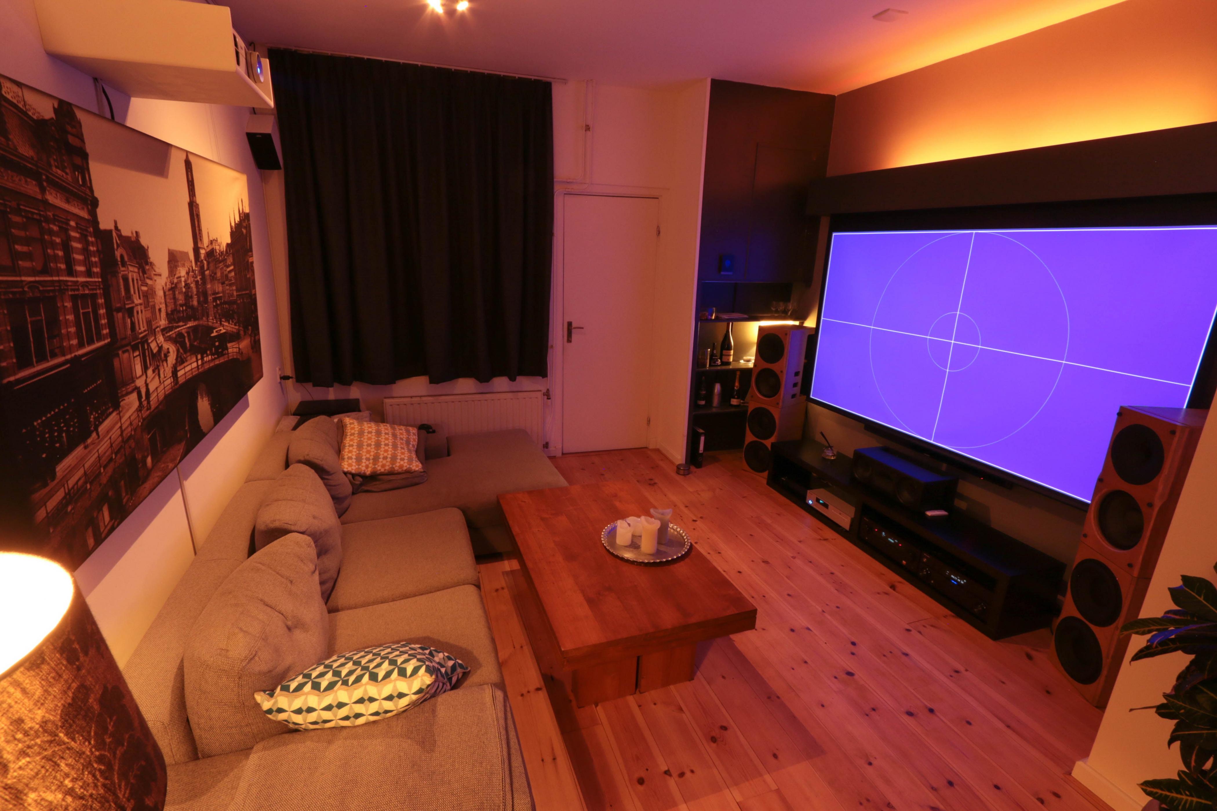
I'm wondering whether what you hear as harshness is caused by the room. I know this is the whole purpose with the directional design, but still the room will play some part in the sound.
You have very little absorption in the room it seems, and also very little diffusion.
Could be good to see the response in the sitting position.
And I would consider adding both some absorption and some diffusion to the room.
Firstly .... super cool project
.... I simply need to try this ...... but need time Maybe it is stated in the above, but the measurements you show, are these in room response?
I'm wondering whether what you hear as harshness is caused by the room. I know this is the whole purpose with the directional design, but still the room will play some part in the sound.
You have very little absorption in the room it seems, and also very little diffusion.
Could be good to see the response in the sitting position.
And I would consider adding both some absorption and some diffusion to the room.
Jag768
Firstly .... super cool project
Maybe it is stated in the above, but the measurements you show, are these in room response?
I'm wondering whether what you hear as harshness is caused by the room. I know this is the whole purpose with the directional design, but still the room will play some part in the sound.
You have very little absorption in the room it seems, and also very little diffusion.
Could be good to see the response in the sitting position.
And I would consider adding both some absorption and some diffusion to the room.
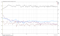
The waterfall plots are made from near field outdoor measurements, using no baffle (woofer on the ground, facing upwards).
Also inroom i had some peaking response in the 500 - 1000Hz region, which did not show in a gated farfield measurement (so quasi anechoic). Merely attunuating these peaks did not suffice. The room is actually quite well treated, just above the sofa behind the canvas there's 80mm thick high denisity rockwool hidden.
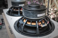
Yesterday i installed the Dayton rs270's. I don't notice any harsnesh in the midrange anymore with these units. Measurements (and more listening) will follow.
Attachments
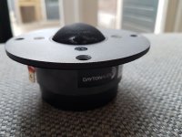
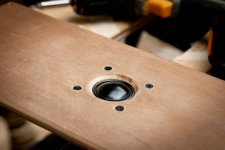
Just before leaving for vacation, i built two waveguides for the Dayton rst-28-a tweeters. One version which fits the tweeter with grill and phase bridge in place. And one version without grill to reduce any space left between tweeter edge and start of waveguide. Ill leave them to dry and make some measurements when i get back.
Attachments
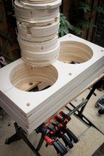
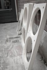
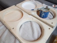
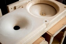
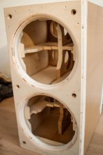
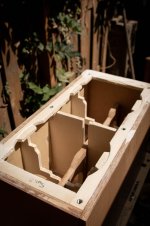
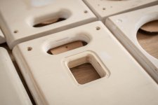
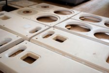
So, another update. Lot of work done. See attached images
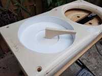
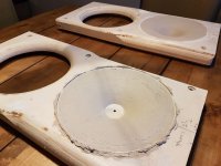
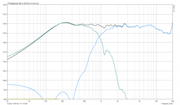
Updated the bracing of my subwoofers (also made a new baffle and rear side). And smoothed the waveguides and fabricated a new faceplate for the Dayton RST-28 tweeters which fits the waveguide throat. And i made a new crossover filter for the Dayton rs270 / rst-28 combi. The 900Hz xover using LR 4th order (acoustic) slopes, turned out to be the winner.
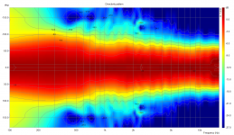
The phase overlap was excellent, resulting in good summing. I measured distortion using a 92dBspl sine sweep @ 1m. No rising distortion for @ xover freq was apparent for the tweeter.
And most importantly, the resulting polar response shows an improved constant directivity over the previous design using the B&C DE250. The dayton RS270 narrows at a lower frequency than the Beyma 10g400, however this is overcome by the lower xover frequency (900 vs 1200hz).
Next on the to do list is re-doing the multi sub setup using multi sub optimizer. My room had some acoustic changes (new doors, change of floor type). And after that all 8 new panels (4 baffles, 4 rear sides) need a finish
Updated the bracing of my subwoofers (also made a new baffle and rear side). And smoothed the waveguides and fabricated a new faceplate for the Dayton RST-28 tweeters which fits the waveguide throat. And i made a new crossover filter for the Dayton rs270 / rst-28 combi. The 900Hz xover using LR 4th order (acoustic) slopes, turned out to be the winner.
The phase overlap was excellent, resulting in good summing. I measured distortion using a 92dBspl sine sweep @ 1m. No rising distortion for @ xover freq was apparent for the tweeter.
And most importantly, the resulting polar response shows an improved constant directivity over the previous design using the B&C DE250. The dayton RS270 narrows at a lower frequency than the Beyma 10g400, however this is overcome by the lower xover frequency (900 vs 1200hz).
Next on the to do list is re-doing the multi sub setup using multi sub optimizer. My room had some acoustic changes (new doors, change of floor type). And after that all 8 new panels (4 baffles, 4 rear sides) need a finish
Attachments
-
 config 4 polar.PNG208.6 KB · Views: 537
 -
 config 4 distortion 92 dB(c).PNG79.4 KB · Views: 458
 -
 config 4 summing.PNG91.9 KB · Views: 397
 -
 config 4 phase.PNG73.4 KB · Views: 413
 -
 IMG_0577.jpg559.8 KB · Views: 525
 -
 IMG_0569.jpg773.3 KB · Views: 520
 -
 IMG_0567.jpg375.2 KB · Views: 404
 -
 IMG_0557.jpg294.7 KB · Views: 1,157
Last edited:
Amazing result.
Can you tell some more about your side cut out for the mid ... why the chosen size etc. and the stuffing ... your experience and tuning of the directionality with the amount of stuffing
The low crossover at 900 for a relatively small tweeter ... any harshness at higher levels?
Distortion measures at higher levels (I take it your measurements are not really at 122 db)?
Thinking of using a 7½ inch SB Satori and a SB ring tweeter
Amazing result.
Can you tell some more about your side cut out for the mid ... why the chosen size etc. and the stuffing ... your experience and tuning of the directionality with the amount of stuffing
The low crossover at 900 for a relatively small tweeter ... any harshness at higher levels?
Distortion measures at higher levels (I take it your measurements are not really at 122 db)?
Thinking of using a 7½ inch SB Satori and a SB ring tweeter
Thank you
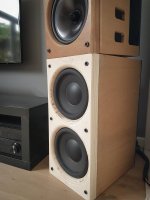
. Side cuts are aprox 1/2 Sd. Increasing the distance between woofer and side port is supposed to degrade midbass off axis performance, but off course lowers the frequency at which LF roll off starts. I used akotherm for stuffing, before that rockwool. It both works, only akotherm is much more precise.I didn't notice any harshness @ 900Hz so far. Distortion measurements were @ 92 dB(C)spl.
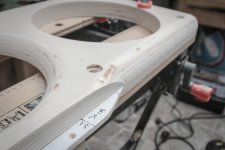
Almost ready for the first layer of paint
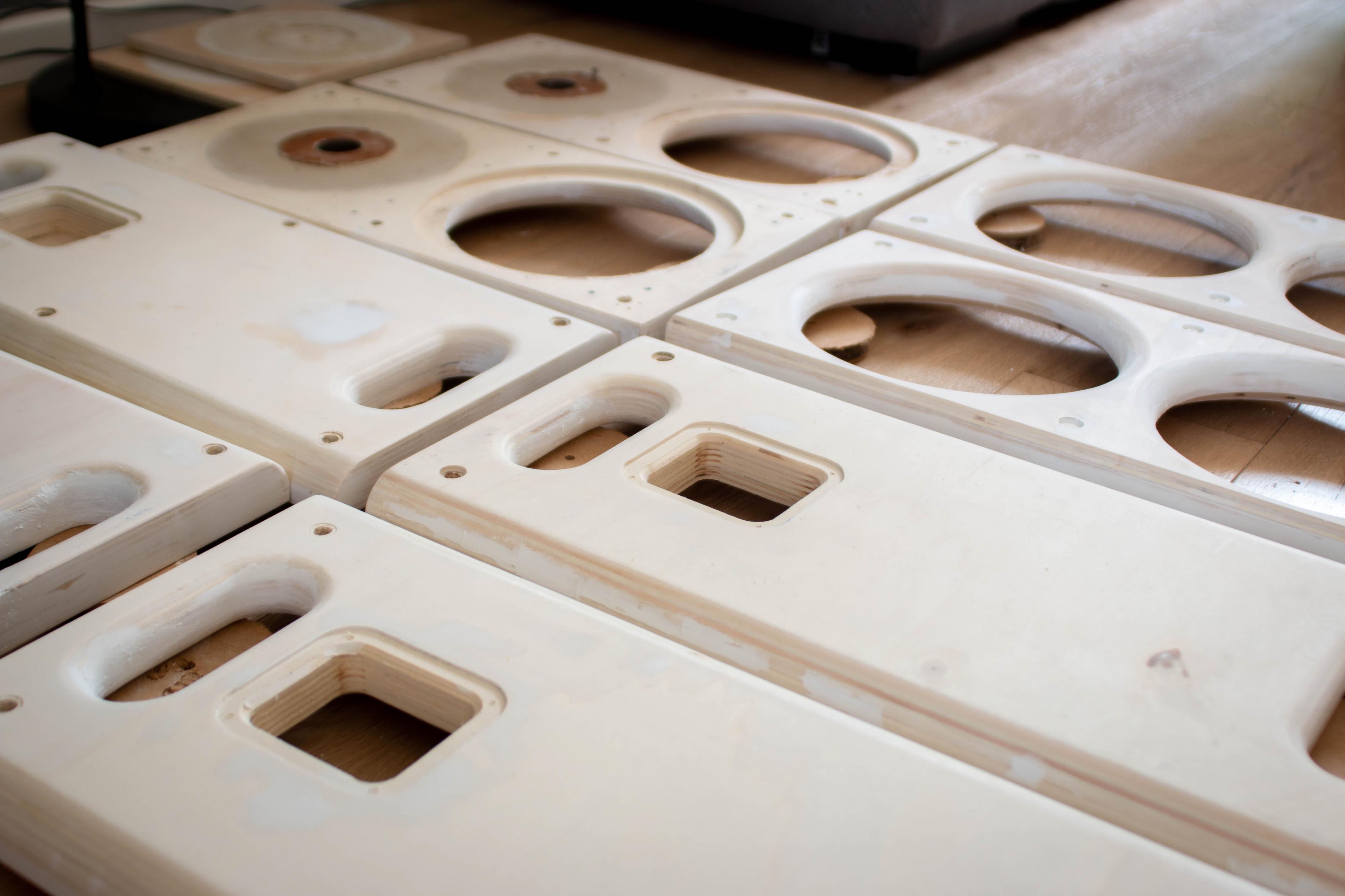
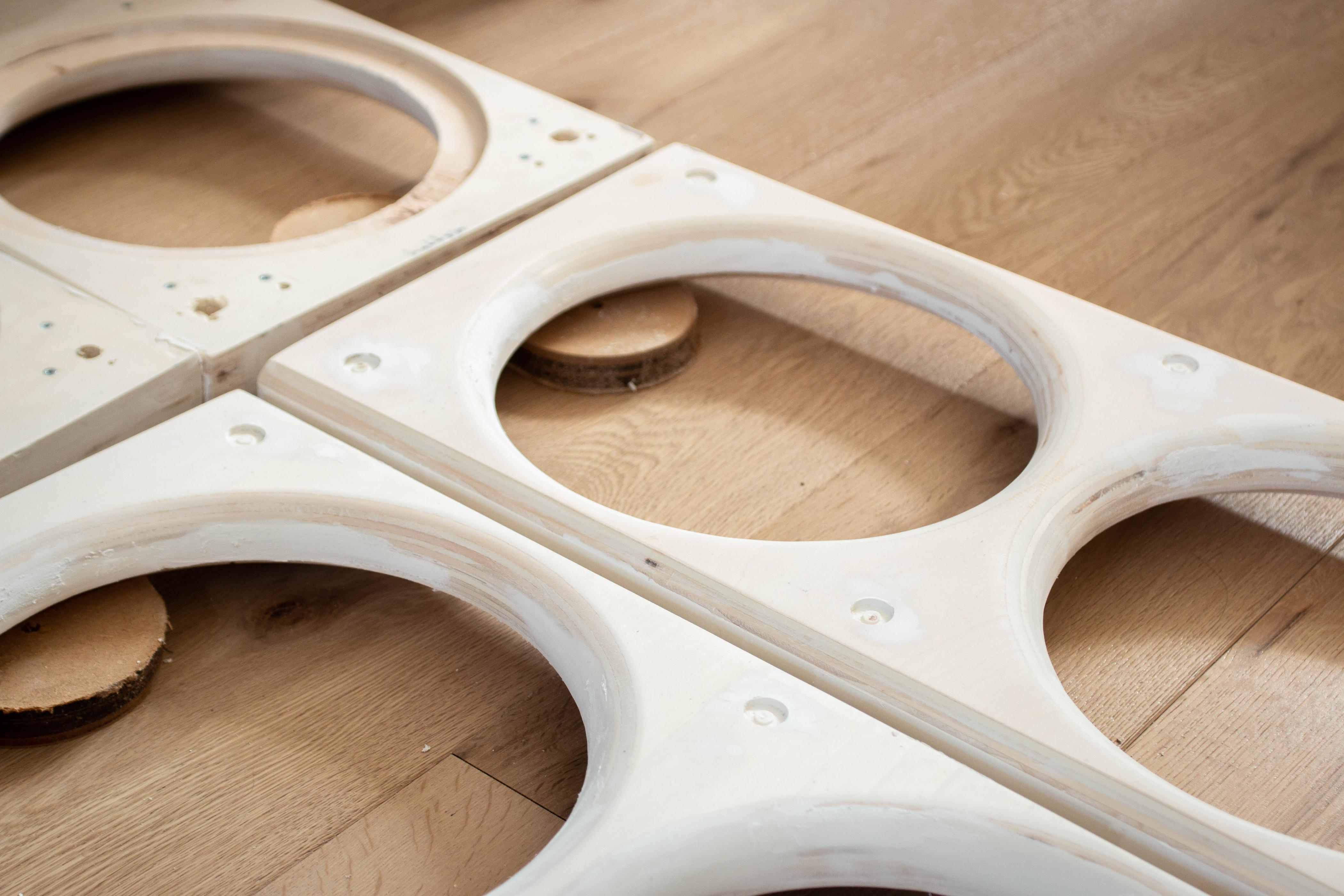

However there's a problem with one of the waveguides, it didn't turn out quite right. The backside collapsed a bit. Still thinking about how to correct it.
However there's a problem with one of the waveguides, it didn't turn out quite right. The backside collapsed a bit. Still thinking about how to correct it.
Attachments

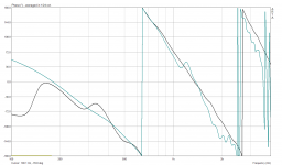
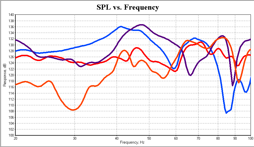
No fun without a good low end, so i re-did the measurements and simulations for the 4 subwoofers.
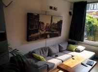
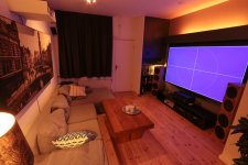
Overview of listening space (old picture, window is replaced by large doors now). 4 subwoofers, each with dual XLS10 drivers in sealed box. One beneath each topspeaker and one on each side of the couch.
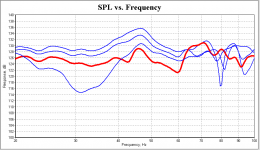
Individual responses of the four (identical) subwoofers at the main listening position; huge variation
Subwoofer position 2, which the right front one, is quite flat. But when you look at the variation in response at the other 3 listening positions, you notice a +/-6dB level difference.
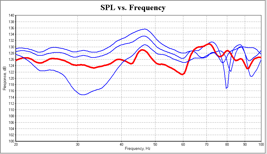
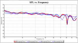
This after running MSO, much better!
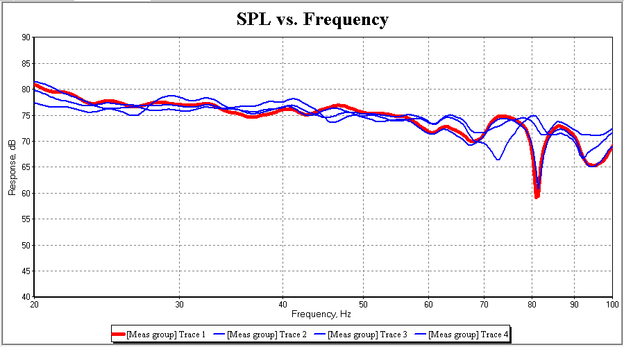
And closeup of integration of mains and subs
Overview of listening space (old picture, window is replaced by large doors now). 4 subwoofers, each with dual XLS10 drivers in sealed box. One beneath each topspeaker and one on each side of the couch.
Individual responses of the four (identical) subwoofers at the main listening position; huge variation
Subwoofer position 2, which the right front one, is quite flat. But when you look at the variation in response at the other 3 listening positions, you notice a +/-6dB level difference.
This after running MSO, much better!
And closeup of integration of mains and subs
Attachments

Impressive result!No fun without a good low end, so i re-did the measurements and simulations for the 4 subwoofers.
Overview of listening space (old picture, window is replaced by large doors now). 4 subwoofers, each with dual XLS10 drivers in sealed box. One beneath each topspeaker and one on each side of the couch.
Individual responses of the four (identical) subwoofers at the main listening position; huge variation
Subwoofer position 2, which the right front one, is quite flat. But when you look at the variation in response at the other 3 listening positions, you notice a +/-6dB level difference.
This after running MSO, much better!
And closeup of integration of mains and subs
I really should build at least 1 more subwoofer (I have 2 now, FR and FL) and test MSO.
/Anton
- Status
- This old topic is closed. If you want to reopen this topic, contact a moderator using the "Report Post" button.
- Home
- Loudspeakers
- Multi-Way
- Full range cardioid