I've been looking at dipole waveguides in Hornresp and seem to be finding that toroidal waveguides along the lines suggested by Geddes offer "horn gain" comparable to the lowering of the dipole peak. I'm not seeing a way to get Hornresp to calculate off axis response but from the wavefront simulation it looks like dipole directivity should be fairly well preserved. Rudolph and Michael, you're both probably a good bit farther along than I am here; what are your thoughts about placing a Neo3 in a roughly toriodal baffle? I'm thinking of something with about a 7cm inner diameter and 17cm outer diameter so that the ring of the toroid would also have a 5cm diameter. Only squashed into a somewhat rectangular shape to better match the Neo3's radiating surface. Not the best description, I know---I'd be happy to render it if someone can suggest a good freeware 3D modeling tool, since the surface is kinda hard to visualize from a 2D drawing.
I have some 3D modeling apps, if you email me a scanned hand-drawn sketch, I can try to draw it up. Google Sketchup is the obvious one to suggest, but I've sometimes found it difficult to draw complex shapes in it. There's also Blender, but that's more for animation AFAIK, and the UI is (IMO) a huge learning curve.
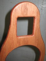
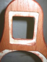
JohnK's Nao Note appears to use a 'rectangular-toroid' kind of shape. Neo3 PDR centered in a 1-1/2" baffle with 3/4" roundovers inside and out. You could probably build one with dowels of whatever diameter and measure it easier than you could model it. Slice the dowel on a table saw to make a slot for the frame to slip into and then cut 4 pieces with 45* angles like a picture frame.
An externally hosted image should be here but it was not working when we last tested it.
I wasn't remembering the Note as having that much depth, but you're right, this is sort of a knock-off.  What I was envisioning had rounder corners, but it occurs to me grabbing some closet rod, PVC, or ABS and throwing it on the mill would be a cheap and quick way to produce a rectangular toroid proof of concept for measurement---wouldn't be hard to make a stretched octagon, either. I'd forgotten about it, but Saurav and villastrangiato have already done something similar in the horizontal plane, though with a smaller diameter, less tight enclosure of the radiating surface, and the focus on 7kHz instead of using horn gain to allow the driver to operate at lower frequency.
Not something I can get to building until October or November, but that just means I have more time to see if I can come up with reasons why increasing the effective dipole separation with a fat baffle like this would cause problems.
What I was envisioning had rounder corners, but it occurs to me grabbing some closet rod, PVC, or ABS and throwing it on the mill would be a cheap and quick way to produce a rectangular toroid proof of concept for measurement---wouldn't be hard to make a stretched octagon, either. I'd forgotten about it, but Saurav and villastrangiato have already done something similar in the horizontal plane, though with a smaller diameter, less tight enclosure of the radiating surface, and the focus on 7kHz instead of using horn gain to allow the driver to operate at lower frequency.Not something I can get to building until October or November, but that just means I have more time to see if I can come up with reasons why increasing the effective dipole separation with a fat baffle like this would cause problems.
The membrane is rectangular so I'd think you'd want to keep the waveguide rectangular as well.it occurs to me grabbing some closet rod, PVC, or ABS and throwing it on the mill would be a cheap and quick way to produce a rectangular toroid proof of concept for measurement---wouldn't be hard to make a stretched octagon, either
I've been looking at dipole waveguides in Hornresp and seem to be finding that toroidal waveguides along the lines suggested by Geddes offer "horn gain" comparable to the lowering of the dipole peak. I'm not seeing a way to get Hornresp to calculate off axis response but from the wavefront simulation it looks like dipole directivity should be fairly well preserved. Rudolph and Michael, you're both probably a good bit farther along than I am here; what are your thoughts about placing a Neo3 in a roughly toriodal baffle? I'm thinking of something with about a 7cm inner diameter and 17cm outer diameter so that the ring of the toroid would also have a 5cm diameter. Only squashed into a somewhat rectangular shape to better match the Neo3's radiating surface. Not the best description, I know---I'd be happy to render it if someone can suggest a good freeware 3D modeling tool, since the surface is kinda hard to visualize from a 2D drawing.
best probably to go back to my "bunch of pretty pictures" :
http://www.diyaudio.com/forums/multi-way/103872-geddes-waveguides-66.html#post1927587
It may give a good clue how a round overs works in relation to radiating area and frequency band affected.
Michael
Thanks, Michael. I'll have to run AxiDriver sims when I get back from vacation.best probably to go back to my "bunch of pretty pictures"
In a line source, probably. In this case the application I'm interested in is a point source so my guess would be the optimal profile encourages more dispersion at the corners than it does along the short sides and, in turn, than along the long sides so as to better match the dispersion of the midwoofer crossed in below the Neo3. It's not clear to me what the preferred taper for these characteristics would be but determining it can wait until after the basic concept's been validated. The Neo3's low aspect ratio compared to the Neo8 and Neo10 is convenient here.The membrane is rectangular so I'd think you'd want to keep the waveguide rectangular as well.
I have written down what I (believe to) know about the relation between driver size and baffle size aka "dipole length". You can download it as a PDF from my site. It is the last download button on that page.what are your thoughts about placing a Neo3 in a roughly toriodal baffle?
If you look at fig. 3.12 and 3.13 in conjunction with fig. 1.12, you see how the dipole pattern blooms into an increasing number of "petals" with alternating phase. When the dipole length increases, the blooming starts at lower frequencies - the dipole pattern can look like two interwoven daisy blossoms with many petals as shown below. I don't know if this is a good thing or bad.
Your toroid needs to separate the front and rear radiation of the dipole before the blossoming starts. Too early, and you get a premature beaming - too late, and you get too many side lobes. Probably you need to ask JohnK how he arrived at the right point. I guess that the waveguide can't get much deeper/wider than he did.
Rudolf
Attachments
Thanks Michael,
I wanted to write it down for people who feel more at ease with pretty pictures and diagrams than with math equations (where I'm rather limited too).
These days I happened to get a glimpse of some Orion++ off-axis measurements. Above 1 kHz they don't look terribly different from the simulations I show in fig. 4.13. At 1-6 kHz both are very much in the same 6 dB corridor. That makes me believe that I'm not completely off the mark.
Rudolf
Yup; the question I'm interested in answering is whether a good balance exists. Results from horns suggest there should be such a profile, though finding it seems likely to be nontrivial.Your toroid needs to separate the front and rear radiation of the dipole before the blossoming starts. Too early, and you get a premature beaming - too late, and you get too many side lobes.
The Neo3 on the Note is crossed at 6kHz whereas I'm curious about the possibility of lowering the cross from the 1.8kHz my nude Neo3s are currently set to. A two or three octave shift in target frequency should allow some freedom for a different waveguide design, particularly as I'm not trying to match the high frequency directivity of a ScanSpeak 10F and the crossovers are quite different.
I've been meaning to ask; what tool did you use for the simulations in chapter 4?That makes me believe that I'm not completely off the mark.
4.1 is done with Edge. Chapters 4.2 und 4.3 are simulated with Boxsim, a german program that has been developed in close partnership with the Visaton driver factory. The factory measured phase, response and impedance data of most Visaton drivers can easily be imported. Boxsim has not been developed with dipoles in mind, but there is a hack that enables "good enough" dipole simulations.... what tool did you use for the simulations in chapter 4?
Rudolf
Thanks; have to look at Boxsim too sometime. Too many tools, not enough time.
As an aside, I've been trying to find the origin of the toroidal dipole baffle idea. Earl's remarks here are probably close. A hyperbolic-exponential throat is probably viable as well, but I'll start the build with just a torus.
As an aside, I've been trying to find the origin of the toroidal dipole baffle idea. Earl's remarks here are probably close. A hyperbolic-exponential throat is probably viable as well, but I'll start the build with just a torus.
The faceplate of those drivers is 194 mm wide - 3 times the Neo3. You don't want to see the polars of those Raal dipole tweeters.
Rudolf
The faceplate of those drivers is 194 mm wide - 3 times the Neo3. You don't want to see the polars of those Raal dipole tweeters.
Rudolf
... room for improvement ...
Even Aleksander has to learn dealing with dipole issues...
Michael
There have been some attempts lately to make dipole tweeters work up to high frequencies with constant directivity. How high can we go, if the tweeter housing is already almost as small as its radiating area?
I would like to demonstrate the issues involved with an idealized 1 inch circular tweeter. I am using some Boxsim simulations to show things detached from specific driver peculiarities like FR and dome breakup modes.
Let’s start with the mathematical dipole model – first for a dipole distance of 2,5 cm to keep things within 20 kHz:
This is equivalent to this Linkwitz figure.
A 1’’ tweeter would have a physical diameter of at least 2,5 cm. This would lead to a dipole distance of 1,25 cm. As a 2-point source this would sim like this:
Of course a tweeter is no 2-point source. Let’s first move to a dipole point source on a 25x25 mm square baffle (Boxsim can’t do circular baffles).
We can see that the dipole peaks are slightly lower in frequency because a 25x25 mm baffle is more like a 28 mm disc than 25 mm. More important by far is the change in directivity that is introduced by the baffle. The dipole 8 gets sort of slimmer.
Since a real tweeter is not a point source on a baffle, we make the cone/dome/foil as wide as the baffle. Note that our model is working as a dipole membrane in a housing with no depth now. Any real world tweeter would have to be larger:
Note how the dipole 8 gets even slimmer than before and how the dipole peaks move to even lower frequencies. Strangely the 60 deg peak is at a lower frequency than the on-axis peak. Same for 30 deg. How come? The next diagram shows why by overlaying the last two diagrams:
The wider source starts to beam – lower in frequency at wider angles. From a certain frequency up the directivity of the tweeter is no longer controlled by the dipole function but by the tweeter diameter. The next diagram shows this relationship at the first dipole peak:
A monopole tweeter would have a main beam to the front of almost the same contour as the figure 8 of the dipole. This would be true for any driver whose radiating area is as large as its baffle – regardless of size. Any attempt to manipulate the radiation at the sides of the baffle is quite fruitless for frequencies above the first dipole peak – they don’t show up any longer at the sides.
The only cure is to move the first dipole peak up by making the tweeter smaller. Above the first dipole peak all compact drivers will move from the (constant) directivity of the dipole 8 to the frequency dependent directivity of a beaming driver.
That’s how I see it.
It seems to me that a dipole tweeter defeats the very purpose of constant directivity. Unless the rear radiation is restricted to a reflector, presumably a parabolic one at that, won't that radiation result in reflections whose directions are difficult or impossible to control and will also be a function of frequency? Am I the only one who sees an inconsistency here?
- Home
- Loudspeakers
- Multi-Way
- On the directivity of dipole tweeters