... one of the longer analyses of the Dallas Rangemaster (if I find the URL i'll post it)
Chapter 10.8.5.5 of “Physik der Elektrogitarre” (Physics of the Electric Guitar) by Dr. Manfred Zollner, the English translation by Tilmann Zwicker is available on Gitec here
Speaking of Tsundoku (or reading-to-do) that's another 1,200 pages onto the pile (along with, so far this year, two sets of essays by Umberto Eco, my long-lost copy of Pirsig's "Zen.." and some more de Botton
") )
)
Last edited:
That book looks extremely interesting, I've bookmarked it.
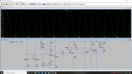
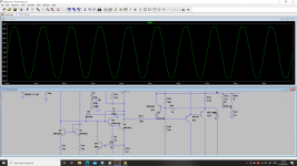
I've had some time to play around with the Baker Clamp in LTSpice and I think that, due to the emitter follower, I only need one diode. The diode seems to quite dramatically improve clipping behaviour. I've attached screenshots of clipping with and without the Baker clamp.
Thanks,
James
I've had some time to play around with the Baker Clamp in LTSpice and I think that, due to the emitter follower, I only need one diode. The diode seems to quite dramatically improve clipping behaviour. I've attached screenshots of clipping with and without the Baker clamp.
Thanks,
James
Attachments
Hi,
I've made some alterations to the schematic and PCB and I have a few questions I was hoping someone might be able to help with.
-What is an appropriate power rating for the Zobel resistor? I've got a 5W in there at the moment but it seems that a lot of designs use much lower. I've also currently got a ceramic zobel capacitor but, looking around, polyester seems to be more common.
-Should I ground the Zobel network to the power ground or the signal ground? The power ground is 'dirty' but I'm not sure if this will be the problem for the passive Zobel network.
-Should I include an output inductor? I used one on my breadboard design but I'm not sure it's necessary, a lot of designs don't have them and since it's only going to be driving a single speaker, it's unlikely to meet a very capacitive load.
-Should I add additional low value ceramic decoupling capacitors to the power rails? If so, where should they be mounted? Near the point of power entry or near the input stage?
-Is my choice of VAS transistor (MPSA42) appropriate or would it be safer to go for a BD139 for better power dissipation, retaining the MPSA42 for the preceding emitter follower?
-I am now thinking of mounting the transistors on aluminium angle bracket fixed to the board, like TO3 devices. I think this will make assembly and mounting easier than having to line up the board standoffs and holes for mounting the transistors directly to the heatsink. Is 3mm an appropriate thickness of aluminium to use? On the subject of heatsinks, in testing, the driver transistors barely got warm. I have included separate heatsinks for them anyway, is this overkill or sensible?
-Is 2oz copper going to be necessary for the PCB? I was hoping not as it's substantially more expensive but if it is, it is. I have also designed the power supply PCB and output jack pcb (containing the jack and the current sense resistor). I have made the tracks very very wide on these using copper fill in the hope that 2oz copper will be unnecessary for these. My only worry is that, although the tracks are wide, the actual solder pad presents a bottleneck and 2oz copper will be necessary anyway.
I know it's a lot of questions, many thanks in advance to anyone who has the answer to any of them!
Thanks,
James
Attachments
Load current is one of the highest currents in the circuit. I've found it best practice to have it return directly to common point without sharing its route with any other return currents. I treat zobel circuit as part of the load (which it is) so its ground return current (although low under usual conditions) returns to common point the same path as the higher load current. You can simply wire the zobel network across the output terminals. (And yes, that method works with CFB as well).
Last edited:
Thanks for the reply. So you wouldn't have any Zobel network on the board itself? Is there not a danger of the amplifier oscillating? In the case of mounting it across the output terminals, I could combine it on the board with the output jack and current sense resistor. I think even with two 5W resistors, the small board would be supported well by the jack alone.
What do you think regarding resistor power ratings and capacitor types?
Thanks,
James
What do you think regarding resistor power ratings and capacitor types?
Thanks,
James
James, I think with the level of build you're planning, go with the 5W rating for the zobel and current feedback resistors. Considering your expected output power, there's no real savings in going to a 2 W, and you want a reliable device that is not at the power limit when you peak your output power. Even if it's a momentary peak to 70 W, you have the baker clamping circuit which will limit, but then why worry about the Zobel and current sensing resistors possibly not holding up?What do you think regarding resistor power ratings and capacitor types?
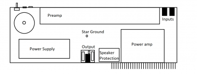
Yep, there's going to be a speaker protection board with DC detection and turn on delay using a MOSFET relay. I'm planning on having it right between the power amp board and the output jack. I made a quick sketch of how I'm imagining the chassis layout at the moment.
Thanks,
James
Thanks,
James
Attachments
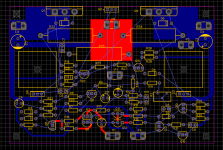
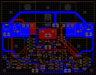
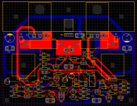
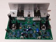
I think I'm pretty close to completion on the power amp board now. I've removed the Zobel and rearranged things a bit so that the power transistors are now mounted flat on aluminium angle against the board. I am planning to use 3mm 30x30mm aluminium angle fixed to the top of the board with the three small screw holes. The power transistors and Vbe multiplier will be bolted down on the aluminium bracket. I have made the holes in the PCB large so that the screw heads can pass through the board so the transistors are just screwed to the aluminium angle, not the PCB as well. I have used 0.5mm small signal traces, 1mm for power, ground and larger currents and large polygons for big currents. I am going to have the board made in 2oz copper. All connections to the board are made via Faston connectors.
The only thing I'm having trouble with is the placement of the power ground connection. it is currently situated at the top next to the Vbe multiplier but this isn't a great position for it. Any Ideas?
Thanks,
James
The only thing I'm having trouble with is the placement of the power ground connection. it is currently situated at the top next to the Vbe multiplier but this isn't a great position for it. Any Ideas?
Thanks,
James
Attachments
Hi,
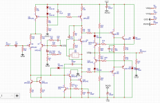
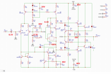
I've just been getting a parts list together for the power amp and I've come up with the following capacitor voltage ratings (marked in red on the schematic). Do these seem reasonable?
I realise that the 50V ratings on the ceramics are excessive but I already have these in C0G with that voltage rating. I know going too high on electrolytics is a problem (hence why I've tried to use the correct rating for those) but are there any issues with ceramics?
Thanks,
James
Attachments
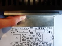
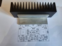
I've now got a problem with the heatsink. I've attached a picture of the arrangement (with a printout of the PCB) of the PCB, bracket and heatsink. The problem is that the surface of the heatsink is not straight so the bracket does not mate properly with it. The second photo attempts to illustrate the problem.
Is this a common problem or should I return the heatsink and expect a replacement to be flat? I suppose I could get an engine shop to skim the surface flat but I'd rather not have the extra expense.
Is this a common problem or should I return the heatsink and expect a replacement to be flat? I suppose I could get an engine shop to skim the surface flat but I'd rather not have the extra expense.
Attachments
Hi,
I've already got the boards made so I'm going to stick with this arrangement this time. I probably will go for direct mounting next time though.
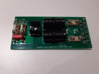
I managed to assemble the boards (power amp, power supply and speaker protection) over the past couple of days. The speaker protection board is working as desired, all aspects of it appear to function correctly.
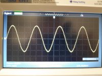
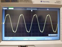
The amplifier is also working. The only problem I am having is with clipping. I have attached pictures showing the progression of a sine wave into clipping. It starts out looking fine, then develops some distortion on the lower half and then exhibits the strange clipping behaviour that looks like rail sticking in reverse.
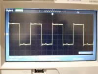
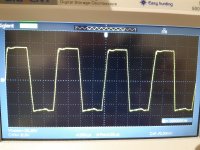
I have also attached pictures of the square-wave output.
Any ideas what could be causing this?
Thanks,
James
I've already got the boards made so I'm going to stick with this arrangement this time. I probably will go for direct mounting next time though.
I managed to assemble the boards (power amp, power supply and speaker protection) over the past couple of days. The speaker protection board is working as desired, all aspects of it appear to function correctly.
The amplifier is also working. The only problem I am having is with clipping. I have attached pictures showing the progression of a sine wave into clipping. It starts out looking fine, then develops some distortion on the lower half and then exhibits the strange clipping behaviour that looks like rail sticking in reverse.
I have also attached pictures of the square-wave output.
Any ideas what could be causing this?
Thanks,
James
Attachments
Hi,
There is a 10n + 10R Zobel network on the output board, by the jack. I'll have a look at what the V-I limiting transistors are doing, perhaps they are switching on momentarily on transients.
I haven't measured the bandwidth yet but I'll do this when I next get a chance to do some testing (probably a couple of days).
I've tested it with a guitar and to me, it sounds pretty good. Obviously it doesn't have a preamp yet so it doesn't sound great but it's got the low-end resonance that I was going for so I'm optimistic about how it will sound when finished. I haven't heard it clipping though and this is where I'm worried it will sound ugly, due to what I observe on the oscilloscope. I'm not really able to drive it to clipping here but when used to a live performance, this may occur.
Thank for all the suggestions,
James
- Home
- Live Sound
- Instruments and Amps
- Solid State 'AC30' clone