Do you know or have a list of the missing component values?It was on ESP website too (project 47) but has been removed because the author sell the right to a manufacturer but I saved teh files 20 years ago 😉
Thanks.
I would suggest knocking down some of the higher frequencies by increasing for example C12 to 100 or 220 pF, see if it helps, then try also C3 and C15. CheersI'm still getting what I consider too much hiss on the clean sound.
Hi,
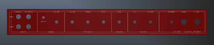
I've now finalised the preamp design (attached) and the boards are being made by JLCPCB right now. Fingers crossed everything works when it arrives! I've started working on the front panel in Front Panel Designer and I'm going to have it engraved by Modulus Amplification. It needs a few tweaks but I'm pretty happy with how it's looking so far.
Once the preamp boards have arrived and been assembled and tested, I can begin work on the chassis. I'm going to order a 'C' type custom chassis from Modulus Amplification. They say that they can do square cutouts for transformers so I'm hoping they can do one for mounting the power amp to the heatsink.
It should start looking a bit more like a guitar amp soon, with any luck!
Thanks,
James
Attachments

Looking great on the preamp and panel design. I noticed you did increase the C3 and C12 value to 10nF, did it help reduce hiss/noise?
Hi,
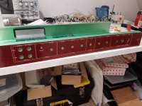
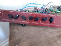
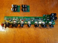
Due to various other commitments, I haven't been able to work on the amplifier for a while but I should be able to get back to working on it fairly soon. There was a bit of progress today as the chassis and front panel arrived, both from Modulus Amplification. The chassis is aluminium and has a rectangular cutout for the power transistors to mount to the heatsink. The front panel is engraved acrylic and looks very good indeed. As you can tell, I've modelled it after the AC30 front panel. I'm particularly pleased that all the holes line up correctly with the preamp board! I've attached pictures of the panel and chassis, along with the preamp board which is now assembled and tested. Hopefully I can get some more work done on it soon and I'll keep you updated!
Thanks,
James
Attachments

Agreed. Super cool.... I can't be alone in thinking that if you were to offer a set of boards (once you are satisfied) in the group buy area or even files for those of us that have had boards made... well.... DIY heaven. Having built several tube amps... this project is very enticing...
Hi,
Sorry, I've only just seen these two comments. I'm really glad to see that my project has captured some interest. Unfortunately, work on the amp has just kept being pushed back as I've had a very busy time with work and other things and it always seems to get pushed to the bottom of the pile. I have returned to working on it now and am aiming to get the chassis finished as a priority, then onto the cabinet when I have the opportunity.
I have made some progress in the past week after not doing anything for a long time. I was actually pretty shocked to see the date on my last post as it seems like virtually no time has passed at all and I've been saying 'I'll get round to it soon'!
I've now drilled out the front of the chassis and ordered the remaining parts needed to assemble it. I dropped the heatsink and amplifier module off at the machine shop at the start of the week to be skimmed flat, drilled and tapped. Once I get it back, I'll be able to assemble the power amplifier onto the heatsink and mount the complete unit in the chassis.
Like I said, I'm hoping to have the chassis complete and working in the next week or two and I'll post the results here when I'm done.
Thanks,
James
Hi,
I've now almost finished assembling the chassis. The machine shop took a long time to get the heat sink done as they were very busy but I got it back a few days ago. I've drilled all the necessary holes and fitted most of the boards and other components. I'm just waiting for some screws to arrive so I can fit the power amp to the chassis and then I can wire it all up and the chassis will be complete. I aim to have it all assembled by the end of the week so, assuming it all works, I can move onto the cabinet.
The cabinet will probably take a while to complete but with the chassis nearly done, it's moving in the right direction!
Why don't you just try clone a real AC15 insted with tubes? Much easier to make with tubes and actually better sound!
A valve AC15 is something that I could just buy off the shelf. Granted, it would be possible to build a higher quality version than those currently in production.Why don't you just try clone a real AC15 insted with tubes? Much easier to make with tubes and actually better sound!
This project, to me, is more unique and challenging.
Beautiful project and flawless execution, Congratulations.
Now we need the Cabinet step by step hread 😉
And some tasty samples.
Now we need the Cabinet step by step hread 😉
And some tasty samples.
Thanks for the comments. I made some progress on the cabinet today. I just need to drill the holes in the back and then it will be finished structurally. The bit on the back that sticks out is where the heatsink is and I'm going to make a cutout and cover it with coarse mesh. I wanted the heatsink to have some protection from being knocked while still having airflow and this seemed like the best solution.
I've wired up what I can on the chassis but I'm still waiting for the screws so haven't been able to fit the power amp yet.


I've wired up what I can on the chassis but I'm still waiting for the screws so haven't been able to fit the power amp yet.
I'm not sure, actually. Certainly lighter than a real AC15. The alnico speaker is light and the chassis can be balanced on one hand. The cabinet isn't as light as some but is pretty standard. Overall I think it will be reasonably light amp though I can't put a figure on it.Nice cab! How heavy do you think it'll be fully assembled?
This is a great thread, and it will be very informative when I finally get around to building my own amp. I have designed from scratch a solid state preamp for guitar/bass, quite a bit more complicated than yours, it pairs Rod Elliot-style soft clipping with FET clipping (with a Fetzer-valve circuit on the clean stage and an opamp forcing a source reference voltage on the drive stage), optional and independently switchable pre/de-emphasis to reduce potential low-frequency IMD and allow higher gains, with a Big Muff tone control for shaping (and a 6-way selector to choose between different mid cuts or boosts), active EQ, vibrato/phaser and spring reverb. Far too complicated haha, but it works on paper (I might add some diode safety clipping to avoid gate conduction on the FETs, but it seems like a gate resistor does the job limiting gate current). For the power amp I'll be using Rod Elliot's guitar amp design, I don't want to reinvent the wheel.
Remember to remove those screws holding sides to top (and bottom) before routing rounded edges, they will destroy the bit if touched.
Small world, I am just now making a very similar cabinet, but smaller (2 x 10")
Ultralight, made out of 12mm plywood, empty cabinet (inclding back panel) only weighs 4.2 kg 😱.
Actually retolexing it, Customer wants it in Brown/Beige colour "because he plays the Blues" 🙄 ; found black Tolex "too Heavy Metal" 😳
He´s paying extra, so no big deal.

also showing one of the (yet unfinished) 10" speakers I make:

EDIT:
IF MosFets though, there is a microns thick glass layer , which won´t stand even 20V or so, even if from static, so .....
Small world, I am just now making a very similar cabinet, but smaller (2 x 10")
Ultralight, made out of 12mm plywood, empty cabinet (inclding back panel) only weighs 4.2 kg 😱.
Actually retolexing it, Customer wants it in Brown/Beige colour "because he plays the Blues" 🙄 ; found black Tolex "too Heavy Metal" 😳
He´s paying extra, so no big deal.
also showing one of the (yet unfinished) 10" speakers I make:
EDIT:
If regular FETs, no big del, they are robust, just plain PN junctions.might add some diode safety clipping to avoid gate conduction on the FETs, but it seems like a gate resistor does the job limiting gate current)
IF MosFets though, there is a microns thick glass layer , which won´t stand even 20V or so, even if from static, so .....
Last edited:
- Home
- Live Sound
- Instruments and Amps
- Solid State 'AC30' clone