Hi,
It arrives that people who have no contact and who don’t know each other have the same idea at the same time. I had the same idea as HOHO and probably, I'm not the only one. I have to start by thanking HOHO for opening this discussion on this topic and also thanking everyone who contributed their knowledge to resolve the issues. After reading this discussion, I am also now convinced that it was not such a stupid idea.
After making the suggested changes, I have still a few issues with this preamp, that I would like to submit to you. So I started with the kit as HOHO but my need is not the same as his. I want to use it with a bass guitar (for a friend). I don’t need lot of gain. I have decreased the output impedance to be able to drive an amplifier with 22kohm input impedance.
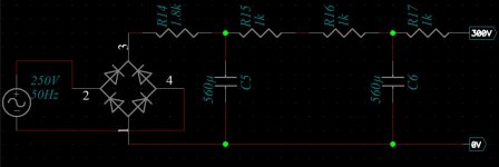
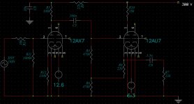
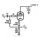
I come to my problem : first, I used a stabilized power supply which provides 12.6 V for heating the filaments and 60 V for the power supply (instead of the expected 300 V). The preamp is quiet and works well, but when I try to get it to work with the 300V power supply that I made, I get a buzzzzzzzzzzz on the amp output. Here are for the moment the diagrams of the preamp and its power supply. I know that my informations are not complete but I will give some others soon to answer to your questions. I would be really happy to have some advice from you. Thank you.
It arrives that people who have no contact and who don’t know each other have the same idea at the same time. I had the same idea as HOHO and probably, I'm not the only one. I have to start by thanking HOHO for opening this discussion on this topic and also thanking everyone who contributed their knowledge to resolve the issues. After reading this discussion, I am also now convinced that it was not such a stupid idea.
After making the suggested changes, I have still a few issues with this preamp, that I would like to submit to you. So I started with the kit as HOHO but my need is not the same as his. I want to use it with a bass guitar (for a friend). I don’t need lot of gain. I have decreased the output impedance to be able to drive an amplifier with 22kohm input impedance.
I come to my problem : first, I used a stabilized power supply which provides 12.6 V for heating the filaments and 60 V for the power supply (instead of the expected 300 V). The preamp is quiet and works well, but when I try to get it to work with the 300V power supply that I made, I get a buzzzzzzzzzzz on the amp output. Here are for the moment the diagrams of the preamp and its power supply. I know that my informations are not complete but I will give some others soon to answer to your questions. I would be really happy to have some advice from you. Thank you.
Attachments
Please see read post #32 of this thread. If you are using the same PCB that Hoho and I used, and you wired it the same way we did, then the filaments need 6.3 volts, not 12 volts. Applying 12.6 volts will quickly destroy (burn out) the valves in this case.ramon69 said:...a stabilized power supply which provides 12.6 V for heating the filaments...
-Gnobuddy
Once you've sorted out the filament voltage problem, you can start to explore the buzz problem.
Regarding which, the first thing I notice is that, looking at your posted schematics, you have no filter cap at the output of your 300-volt power supply. And you also have no filter capacitor where the power supply connects to the preamp (i.e. there is no filter cap for the 12AU7).
This means you have a 1k resistor (R17 in your schematic) in series with the +300V rail, and that will cause unwanted feedback between all four triode stages. This might be contributing to the buzz - in any case, it is very bad practice, and should be fixed.
To fix this, you need to add a filter cap at one of these two locations (output of 300V supply or across 12AU7 power and ground rails). If there is a considerable length of power supply wire in between, add a filter cap at both locations.
The filter cap doesn't need to be huge; I suggest, say, 47uF near the 12AU7, and I suggest wiring a 10nF (same as 0.01uF) ceramic or film capacitor in parallel with the 47 uF electrolytic to provide high-frequency filtering.)
There are other likely causes for the buzzing; is your preamp inside a grounded metal box? If not, the high input impedance will allow it to pick up noise signals from thin air.
Grounding problems can also cause buzzing (also discussed early in this thread). How are you grounding the preamp ground, filament ground, and 300 volt ground? If this is done incorrectly, it can cause buzzing too.
-Gnobuddy
Thank you for your reply.
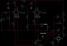
To be more accurate on what I did for the heating of the filaments, here is the complete diagram of my project. Is it correct ? To do this, I removed pin 9 from the socket of each tube. I thought it would be more easy than modify the PCB.
Indeed, there is a considerable length between R10 and R16. I will begin to add a filter capacitor near each resistor as you advised.
Now I have to make the changes. Of course, I'll be back to tell you how it works.
Ramon
Attachments
Nice lateral-thinking.ramon69 said:...I removed pin 9 from the socket of each tube.
") I agree, that solves the heater grounding issues of the PCB very nicely.
I agree, that solves the heater grounding issues of the PCB very nicely.I solved the same problem in a different way, using Russian 6N2P valves instead of 12AX7s. 6N2Ps have 6.3V filaments with no centre tap, and pin 9 is connected to an internal electrostatic shield, which is designed to be grounded. So this PCB works perfectly with 6N2Ps - pin 9 is grounded as it should be, and both ends of the 6.3V heater are floating, so you can decide if, how, and where to ground them or ground-reference them.
To clarify, the 12AU7 currently has no filter cap at all, according to your schematics. So you need to add one filter cap for the 12AU7. Basically from the upper end of R10 to PCB signal ground.ramon69 said:I will begin to add a filter capacitor near each resistor as you advised.
It may be that using only an electrolytic cap here will do the job. But electrolytic caps don't work well at high frequencies because they have too much self-inductance, so adding a small ceramic or film cap in parallel ensures that you still have low supply rail impedance even at high frequencies well above the audio range. This reduces any tendency the 12AU7 has to oscillate at radio frequencies.
I apologize if I'm telling you stuff you already know. It's always a bit of a challenge when encountering a post from someone you don't know on a forum, because I don't know enough about your proficiency in electronics. Maybe you know more than I do, maybe you're a raw beginner just figuring out which end of a soldering iron is which. I don't know, so I try to err on the side of providing detailed information rather than too little.
-Gnobuddy
This is great art!I solved the same problem in a different way, using Russian 6N2P valves...
Ok. It's really clear....you need to add one filter cap for the 12AU7. Basically from the upper end of R10 to PCB signal ground.
There really is no need to apologize. I'm so glad to get some help on this project.I apologize if I'm telling you stuff you already know.
Certainly not.Maybe you know more than I do
To introduce myself quickly, I am a mechanical designer. I have fun doing electronics, mainly hi-fi amps and preamps (easy projects, tubes and solid state). Since my son started to learn guitar, I started this preamp project with which I have a hard time But thanks to you, now I begin to see the end of the tunnel
I hope you and your son get the preamp working soon.
After looking at your schematic again, I have a couple of questions.
1) What's going on with pin 6, 7, and 8 on both valves? Are they just floating, or is the schematic duplicated (second channel) using those pins?
Valves are funny things. If you leave a pin unconnected, stray electrons will probably land on it, and end up giving it a large negative charge. I don't know what this might do to normal operation of the other triode in the same glass bulb, and I also wonder if you can accumulate enough electrons on the unconnected cathode to cause failure of the heater-cathode insulation. In general, leaving those pins unconnected seems like a bad idea.
So if those pins are floating now, I suggest changing that. Grounding pin 6,7, and 8 on both valves is probably okay. Or add suitable bias resistors so they duplicate the channel you're using.
2) C6 is supposed to decouple the cathode (pin 3) of the 12AU7 to ground. But R7 prevents this from occurring. Why is R7 there at all?
3) The network R4/R6/R8 looks like it's bootstrapping R4 to raise the input impedance of the 12AU7 stage. But why? There's no need for exceptionally high input impedance here, and besides, C6 is apparently trying to ground pin 3 (though foiled by R7), so that there will be no signal voltage on pin 3 to bootstrap the bottom of R4 anyway.
4) There is some question as to the best place to ground the metal housing (box). If you ground it to the power supply ground, as you showed, then the input jack (ENT) should be isolated from the metal box - either use a plastic jack, or if you use a metal jack, mount it with plastic shoulder-washers so that the jack's metal body does not make electrical contact with the metal box.
There is another option, which is to actually ground the metal box to the input jack (and not to the power supply ground). See fig 15.10 in Merlin Blencowe's PDF document on how to ground valve preamps: The Valve Wizard
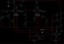
I'm attaching your schematic with some of my suggested changes (I didn't change the grounding location, you may want to experiment to see which of the two schemes gives you the least hum/buzz.) The shocking-pink lines are my suggested changes.
R4, by the way, is a good place to put a "Gain" potentiometer instead of a fixed resistor. A 470k log pot would be a good choice. The pot track is wired exactly where the two ends of R4 go, while the pot wiper goes to pin 2 (control grid) of the 12AU7.
-Gnobuddy
After looking at your schematic again, I have a couple of questions.
1) What's going on with pin 6, 7, and 8 on both valves? Are they just floating, or is the schematic duplicated (second channel) using those pins?
Valves are funny things. If you leave a pin unconnected, stray electrons will probably land on it, and end up giving it a large negative charge. I don't know what this might do to normal operation of the other triode in the same glass bulb, and I also wonder if you can accumulate enough electrons on the unconnected cathode to cause failure of the heater-cathode insulation. In general, leaving those pins unconnected seems like a bad idea.
So if those pins are floating now, I suggest changing that. Grounding pin 6,7, and 8 on both valves is probably okay. Or add suitable bias resistors so they duplicate the channel you're using.
2) C6 is supposed to decouple the cathode (pin 3) of the 12AU7 to ground. But R7 prevents this from occurring. Why is R7 there at all?
3) The network R4/R6/R8 looks like it's bootstrapping R4 to raise the input impedance of the 12AU7 stage. But why? There's no need for exceptionally high input impedance here, and besides, C6 is apparently trying to ground pin 3 (though foiled by R7), so that there will be no signal voltage on pin 3 to bootstrap the bottom of R4 anyway.
4) There is some question as to the best place to ground the metal housing (box). If you ground it to the power supply ground, as you showed, then the input jack (ENT) should be isolated from the metal box - either use a plastic jack, or if you use a metal jack, mount it with plastic shoulder-washers so that the jack's metal body does not make electrical contact with the metal box.
There is another option, which is to actually ground the metal box to the input jack (and not to the power supply ground). See fig 15.10 in Merlin Blencowe's PDF document on how to ground valve preamps: The Valve Wizard
I'm attaching your schematic with some of my suggested changes (I didn't change the grounding location, you may want to experiment to see which of the two schemes gives you the least hum/buzz.) The shocking-pink lines are my suggested changes.
R4, by the way, is a good place to put a "Gain" potentiometer instead of a fixed resistor. A 470k log pot would be a good choice. The pot track is wired exactly where the two ends of R4 go, while the pot wiper goes to pin 2 (control grid) of the 12AU7.
-Gnobuddy
Attachments
Last edited:
Yes, these are used for the second channel. There is no « free » triode in this schematic.1) What's going on with pin 6, 7, and 8 on both valves? Are they just floating, or is the schematic duplicated (second channel) using those pins?
You mean like this : EL34 SE3 ,for the ecc83 ?Or add suitable bias resistors so they duplicate the channel you're using.
This schematic has been drawn with PCAAD. This software allows me to simulate the operation, look at the frequency response, gain,… It's very practical for me. I remind you that I am not an expert in electronics. In my diagram, R7 represent the input impedance of the amp to which this preamp will be connected. This allows me to have the most accurate results possible when I display a Bode diagram, for example. In fact, in the real preamp, R7 = 470 kohm. This resistor is useful to allow C6 to charge when the circuit is powered up and no load is connected at the output of the preamp. Is it right?2) C6 is supposed to decouple the cathode (pin 3) of the 12AU7 to ground. But R7 prevents this from occurring. Why is R7 there at all?
For tube 12 au7, my objective was to achieve a cathode follower. So I was inspired by schematics found on the net. This seemed to be good (for me!). I will take your changes into account.3) The network R4/R6/R8 looks like it's bootstrapping R4 to raise the input impedance of the 12AU7 stage. But why? There's no need for exceptionally high input impedance here, and besides, C6 is apparently trying to ground pin 3 (though foiled by R7), so that there will be no signal voltage on pin 3 to bootstrap the bottom of R4 anyway.
In my prototype, the input and output jack are isolated from the metal box. The ground connexion of each jack is made with wire to the PCB.4) There is some question as to the best place to ground the metal housing (box). If you ground it to the power supply ground, as you showed, then the input jack (ENT) should be isolated from the metal box - either use a plastic jack, or if you use a metal jack, mount it with plastic shoulder-washers so that the jack's metal body does not make electrical contact with the metal box.
Indeed, a potentiometer can be useful. I note your proposal but I will probably implement it later. Thank you.R4, by the way, is a good place to put a "Gain" potentiometer instead of a fixed resistor. A 470k log pot would be a good choice. The pot track is wired exactly where the two ends of R4 go, while the pot wiper goes to pin 2 (control grid) of the 12AU7.
I’m coming back to the problem of the filter cap for the 12au7. In this case of a cathode follower wouldn't it be better to connect it between the bottom of R10 (anode of the tube) and the ground?
Ramon
Okay. That's good! The schematic is misleading, as it shows all those pins not connected.ramon69 said:There is no « free » triode in this schematic.
Okay. Got it now. R7 is not a real resistor on the PCB, but a stand-in for the load the preamp is going to drive.ramon69 said:12 au7...a cathode follower.
If the 12AU7 is being used as a cathode follower, why have R10 at all? A cathode follower doesn't need an anode load. All it does is waste voltage, i.e. it reduces output headroom of the cathode follower...
If you remove R10 (and replace with a short), the added filter cap can go directly from the +300V rail on the PCB to ground on the PCB.
Since you've lowered the gain quite a bit, I think it will be easy to tame the buzz problem once you find the cause. With a little luck, adding the missing filter cap will do most of the job for you.
-Gnobuddy
If the 12AU7 is being used as a cathode follower, why have R10 at all? A cathode follower doesn't need an anode load. All it does is waste voltage, i.e. it reduces output headroom of the cathode follower...
If you remove R10 (and replace with a short), the added filter cap can go directly from the +300V rail on the PCB to ground on the PCB.
Okay. I can therefore take inspiration from the second diagram on this page ? The Valve Wizard -Cathode Follower
I just need to add the filter capacitor to this.
Ramon
Yes, you certainly can! I took the liberty of editing Blencowe's schematic slightly (attached).Ramon69 said:I can therefore take inspiration from the second diagram on this page?
I didn't write in a value for the filter cap, as it is not critical at all. A small electrolytic cap (10uF - 47uF) in parallel with a smaller ceramic or film cap (say 10nF) is my suggestion.
In your case, the unusually high input impedance (created by bootstrapping Rg) doesn't provide any advantage. But the biasing method Blencowe used (splitting the cathode load into two, Rb & Rk ) also increases the output headroom by raising the DC quiescent voltage at the cathode. That's a good thing.
-Gnobuddy
Attachments
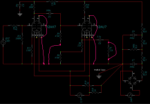
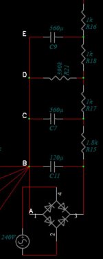
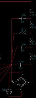
Here we are. After a welding session, I’ve tried again and the bzzzzzzzz is still present. Here is the schematic of my new circuit. I did not take any electrical voltage measurements but I can say that the preamp works well, apart from the hum.
Maybe it's time to look toward the power supply. I don't have any oscilloscope to check the output ripple of the power supply but I'm wondering if my schematic is well designed. Often in power supplies for preamps, in RC filters, there are resistances greater than 10kohm and capacitors less than 100µF. In my circuit, it is rather the opposite. Isn't that a problem? The filtering seems insufficient. I remind you that the preamp is silent with a laboratory power supply.
Ramon
Attachments
Power supply ripple is certainly a possibility, in case there is a soldering mistake or component value error. The power supply design itself looks good (with one major mistake which I'll mention later in this post). You have a lot of filtering, and ripple should be extremely small if built as designed.Ramon69 said:...the bzzzzzzzz is still present...
<snip>
...the preamp is silent with a laboratory power supply.
A basic question, just to be sure: you are using a power transformer to generate your 250 volts AC, right? If you are not using a transformer and are feeding the diode bridge directly from 240V household electricty, the circuit is deadly, and can kill you and/or your son.
No transformer is shown in the schematic, and you haven't mentioned one as far as I can recall, so I'm asking, just to be sure. Please - if there is no power transformer in use, stop all experimenting immediately. Unplug the circuit from the wall without touching it, and do nothing more until you have a power transformer.
Assuming you do have a power transformer, and the circuit is safe: what happens if the input of the preamp is grounded? (Plug in a 1/4" jack with tip and ring shorted, or use a clip-lead to short the tip and ground at the far end of a short guitar cable.)
If the buzz is due to the circuit picking up noise, grounding the input will quiet it. If the buzz is due to grounding problems or power supply ripple, grounding the input will not reduce the buzz.
It is the product of R and C that matters for filtering. In other words, 10k and 100uF produces exactly the same amount of filtering as 1k and 1000uF, or 100k and 10uF, or 1Meg and 1 uF.Ramon69 said:Often in power supplies for preamps, in RC filters, there are resistances greater than 10kohm and capacitors less than 100µF. In my circuit, it is rather the opposite. Isn't that a problem? The filtering seems insufficient.
The difference between these various choices is mainly the amount of DC current that you can supply. Obviously you can supply a lot more current using a 1K resistor and 1000 uF than from a 1M resistor and 1uF.
What does your simulation software say about your power supply? You should be able to view predicted ripple voltage on the +300V line.
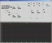
I simulated your power supply in LTSpice, and I don't see any ripple problems to speak of at 4 mA current draw (I was guessing at 1 mA per triode for your circuit.) As you can see in the attached screenshot, there is only about 40 micro volts of ripple at the output. Note the vertical scale is 5 uV per division.
I used C3/R6 to block the DC voltage at the output, so that I could really zoom in on only the AC voltage (ripple) at that location.
The lack of significant ripple is not surprising, as 1k and 560 uF provides some 30 dB of ripple attenuation. You have a second similar stage following the first, so there will be some 60 dB of combined ripple attenuation.
However, there is one simple thing you can do to dramatically reduce ripple voltage even more!
In your power supply design, there will be some 350 volts (peak to peak) of AC ripple at the output of the diode bridge, between pins 1 & 3 in the schematic you posted earlier on this thread.
Normally, there will be a filter capacitor wired directly to the output of the diode bridge. This immediately reduces your 350 volts of AC ripple by a huge factor - a reasonable capacitor size here will reduce it a hundred-fold. So, by omitting this capacitor, you made your power supply ripple about a hundred times bigger than it needs to be!
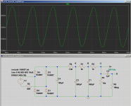
The second attached screenshot shows what happens (in my LTSpice simulation of your power supply) when I add a 100 uF capacitor here, right across the output of the diode bridge. Ripple at the output (node D) reduces from 40 uV to less than 0.4 uV! (Note that the vertical scale is now 100nV per division, which is fifty times smaller than the 5uV/div scale in the first screenshot.)
So, omitting that filter cap at the diode bridge output is costing you a hundred-fold increase in ripple. (However, you have used so much filtering elsewhere in the circuit that even this design mistake doesn't cause a problem; even as-designed, ripple is too small to matter in a guitar preamp.)
There will be one side-effect if you add the missing filter cap: the DC voltage at the output will increase a bit. You may need to re-tweak the series resistor values if you want it to come back down to exactly 300 volts. My simulation puts it at about 315V DC if you add the 100uF filter cap at the diode bridge, and make no other changes.
Keep in mind your modified circuit has only roughly 30 dB of voltage gain, as your second stage is a unity-gain cathode follower. It is not by any means a high-gain circuit, and one would not expect a lot of buzzing problems if the circuit is built properly. So there must be some significant error somewhere. Hopefully that will make it relatively easy to find and fix the fault.
-Gnobuddy
Attachments
Last edited:
...I'm wondering if my schematic is well designed. Often in power supplies for preamps, in RC filters, there are resistances greater than 10kohm and capacitors less than 100µF. ...The filtering seems insufficient.
You sure can get ample filtering with a larger number of much smaller caps.
Another thing is the routing of the big current pulses from rectifier to first cap. Do not connect the children's sidewalks on the highway full of heavy trucks.
Attachments
A basic question, just to be sure: you are using a power transformer to generate your 250 volts AC, right?
I reassure you, the 240 V supply comes from a transformer. A brand new one. The 12.6 V comes from a second winding of the same transformer.
I read the rest of your messages attentively, and will reply to you shortly. Thanks for your expertise.
Ramon
I had grounded the input but the buz is the same.
Now, I have to look at the power supply.
All your explanations are clear. I will had a filter capacitor wired directly to the output of the diode bridge. I will probabely find a 120 or 150µF, rated at 350V, in my drawers.
About the wiring, :
- Is my power_supply_V2 correct or I have to move the grounding point to A, C, D or E ?
- Would it be useful to do the same wiring that the power_supply_V2 ?
First, I'll check my circuit one more time
Ramon
Now, I have to look at the power supply.
All your explanations are clear. I will had a filter capacitor wired directly to the output of the diode bridge. I will probabely find a 120 or 150µF, rated at 350V, in my drawers.
About the wiring, :
- Is my power_supply_V2 correct or I have to move the grounding point to A, C, D or E ?
- Would it be useful to do the same wiring that the power_supply_V2 ?
Keep in mind your modified circuit has only roughly 30 dB of voltage gain, as your second stage is a unity-gain cathode follower. It is not by any means a high-gain circuit, and one would not expect a lot of buzzing problems if the circuit is built properly. So there must be some significant error somewhere. Hopefully that will make it relatively easy to find and fix the fault.
First, I'll check my circuit one more time
Ramon
Attachments
Ramon, regarding grounding options, please see the link to Merlin Blencowe's website that I included in my post #87. I think he (Blencowe) does a far better job of discussing grounding practices than I can.
You mention that your 12.6V heater power comes from a separate winding on the same power transformer. Is the 12.6V winding floating, or is it referenced to ground? If floating, it can cause hum and buzz problems.
There are two common ways of ground-referencing the heater winding:
1) If the 12.6 V winding has a centre-tap, just ground the centre tap.
2) If it does not have a centre tap, wire two equal-value resistors in series across it (say, two 1k resistors in series; the value is not critical.) Then ground the node (the "artificial ground") where the two 1k resistors meet.
The attached diagram shows both approaches.
-Gnobuddy
Attachments
My 12.6V heater power comes from a separate winding. To ground referencing I choosed the second solution with resistors (Remember my postYou mention that your 12.6V heater power comes from a separate winding on the same power transformer. Is the 12.6V winding floating, or is it referenced to ground? If floating, it can cause hum and buzz problems.
Code:
I read. I read. Very instructive ! Especially about the transformer-rectifier-reservoir that you had already talk about.Ramon, regarding grounding options, please see the link to Merlin Blencowe's website that I included in my post #87. I think he (Blencowe) does a far better job of discussing grounding practices than I can.
-Ramon
The simulation is very interesting and shows that the quality of the filtering seems correct. Thank you.
Thank you also for this beautiful metaphor, but I must admit that I find it difficult to transcribe it in terms of circulation of electric currents. Can you be a little more specific, please?
- Ramon
Do not connect the children's sidewalks on the highway full of heavy trucks.
Thank you also for this beautiful metaphor, but I must admit that I find it difficult to transcribe it in terms of circulation of electric currents. Can you be a little more specific, please?
- Ramon
Merlin Blencowe's document on grounding (already referenced) is as specific as you can get.ramon69 said:...Can you be a little more specific, please?
This is a simple, low-gain circuit, and should not be buzzing. But it is, therefore there is some large and obvious mistake in construction.
The trouble is, we are all working blind. You don't have a 'scope, and we (PRR and I) are thousands of kilometres away on the other end of an Internet connection, unable to even see the circuit as you've built it. So I / we cannot tell what the large and obvious mistake might be.
Grasping at straws: how much distance is there between the power transformer and the vacuum tubes? If the Tx is too close, radiated electromagnetic interference might cause part of your problem. In this case, try extending the wires carrying the DC output of the power supply, and moving the entire power supply further away from the 12AX7.
One other thought: what are you connecting the output of this circuit to? Is it plugged into an existing solid-state bass guitar amplifier?
If so, the hum problem may be caused simply because you've added 30 dB of gain at the input of an existing high-gain amplifier. If this is the case, insert a volume potentiometer between the output of your circuit, and the input of the bass guitar amp. Turn it down until the hum goes away - is there still enough gain so the bass can be played through the amp?
Finally, have you measured DC voltages at every pin of both tubes? (Except heater pins). If there's a bad solder joint or other construction mistake, this can help pinpoint it. You don't need any fancy equipment, just a cheap DMM. In the USA I could get a decent usable one for $20 USD, here in Canada I can get one for about $35 CAD. Like this: Auto Ranging Digital Multimeter TRMS 6000 with Battery Alligator Clips Test Leads AC/DC Voltage/Account, Voltage Alert, Amp/Ohm/Volt Multi Tester/Diode, Multi Testers - Amazon Canada
If none of my guesses turn out to be the problem, is there any way you can find somebody local with some electronics knowledge to help? Not easy in the midst of a pandemic, I know.
If nothing else, some clear photos of the entire build might help. Top and bottom views of the PCB, along with overall pics showing position of transformer, input jack, AC power cord, grounding scheme, et cetera.
So far: we know the noise is not picked up from the input. We know there should be very little ripple from the power supply. We know the heaters are grounded. That's all we know.
-Gnobuddy
- Status
- This old topic is closed. If you want to reopen this topic, contact a moderator using the "Report Post" button.
- Home
- Live Sound
- Instruments and Amps
- Modifying a 12ax7 HiFi valve preamp to be a guitar preamp