Sorry, I shouldn't assume you have my project in mind. For me it's _the_ project, for you it's just a conversation (one of many).
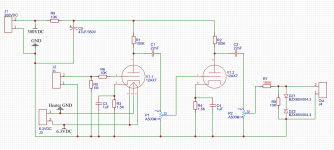
The schematics is exactly what it was with your suggestions a few months back. Attaching it to this message. In the preamp I have two pots. Then my J4 output goes to ADC. So, I will replace R7 with 330K (I've also ordered 360K to try).
And I actually like that I have those pots. I will have another one after the DAC too, to level the output going to the PA. But I'm going to keep the preamp master, it seems to give more flexibility and variations. With the diode clipper at the proper level, I will be able to intentionally drive it to the clipping state with the preamp master volume. It certainly might kill some tubiness, but I will try different clipper versions to see if I like it or not. And it won't kill all the tubines. Right now it sounds very nicely, unmistakenly tubey when I play softly. And I don't really hit the guitar too hard most of the time, I mostly palm-mute when I play. I will experiment further but I see a case when I can be ok with the thing acting tubey most of the time and clipping just the heavy hits.
So, it's not a question of if the valve makes sense or not — even at this stage it makes 100% sense to me and my ears. I've added a speaker impulse response part recently and it's made me extremely happy with the result even without EQ and reverb/delay. It certainly wasn't in vain. Though I've been using only headphones so far to hear it, just because my current setup is very messy to move it around. But once I have it less messy, I'm going to add a transformer, an XLR out (plus the phantom power blocking capacitors) and an output level knob.
Attachments
Thanks! I would worry that my memory is getting worse with age, but in fact, my memory has been terrible since I was in my early twenties.The schematics is exactly what it was with your suggestions a few months back. Attaching it to this message.

If tinkering with DIY electronics starts to look like a long-term hobby, you might consider buying a resistor kit - it will save time, money, and frustration in the long run. Something like this: 1280 Pieces 64 Values Resistor Kit, 1% Assorted Resistors 1 Ohm-10M Ohm 1/4W Metal Film Resistors Assortment with Storage Box for DIY Projects and Experiments: Amazon.ca: Tools & Home Improvement...330K...360K...
Fair enough, your project, your preferences!And I actually like that I have those pots. I will have another one after the DAC too, to level the output going to the PA.
Funny thing - I've been playing guitar for most of 35 years, and have been using left-hand muting when appropriate for most of that time. But I never used palm-muting - until last week!I mostly palm-mute when I play.
What happened was that I was watching an old film ("Greenfingers") on NetFlix, and in the film heard a song by U2 that I'd never heard before (All I Want Is You): YouTube
I liked the song, and wanted to play and sing it at one of our weekly jams, so it was time to learn how to palm-mute, so I could play the introduction to that song properly.
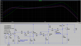
I've been designing an analog electronics one (speaker emulation filter), for a project that's already taken me way too long. The screenshot shows the circuit and the simulated frequency response curves it should generate, which are tweakable to cover a reasonable range of guitar sounds.I've added a speaker impulse response part recently...
This is going to be used as part of a small, portable, DIY battery-powered P.A system that will accept two microphones and one guitar, for quick and easy jams. The whole plan started when I found two Sony bookshelf-sized boom box speakers in a thrift store for $4 and brought them home, convinced that I could do *something* useful with them.
I used discrete JFETs and BJTs throughout, mainly because I think they clip more gracefully than op-amps do, and they work fine for this job. Unwanted clipping has a way of happening when live guitar is involved, so it's probably a good idea to have something that clips less harshly than an high gain op-amp.
-Gnobuddy
Attachments
I suppose the impulse response thing is where the digital technology truly shines. Seems like it's being widely adopted by the manufacturers. Not just for the cab simulation, but for the reverbs and instruments (new Fender Acoustasonic Telecasters, for example). I guess it's much deeper and realistic than just shaping the frequency curve. I was amazed how cool it sounds (in my headphones at least).
Anyway, I'm going to take some more time to get the diodes, to try to find the most suitable clipping solution and to write some code. After that, I'll try to publish some sounds.
Thanks again!
Anyway, I'm going to take some more time to get the diodes, to try to find the most suitable clipping solution and to write some code. After that, I'll try to publish some sounds.
Thanks again!
You can make a crappy filter with digital, or with analogue. You can make a good filter with digital, or with analogue. It's not the implementation technology, it's how well the job is done!I suppose the impulse response thing is where the digital technology truly shines.
The digital way is extremely flexible, as I'm sure you know: change the filter constants, and you can create a new filter response at will.
Unfortunately, using DSP also makes it easy for the clueless (or uncaring) to create really nasty-sounding filters, because you just stuck a mic in front of a speaker, generated Fourier coefficients, and stuck them into your DSP filter, without looking closely at the filter response, or understanding how that affects the sound quality of the device.
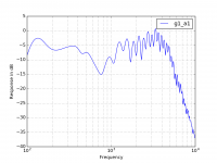
The attached image shows the measured frequency response of the speaker emulation filter in a certain commercial DSP modelling guitar multiFX box. The very ugly and very ragged frequency response creates a harsh and ear-fatiguing sound; those numerous sharp peaks and dips are not from the speaker, but the result of poor-quality speaker measurement without the use of an anechoic chamber or proper gating of the measured impulse response.
That measured frequency response curve came from here: Automating the Measurement of Frequency Response
In mass production, digital is cheaper. Precision caps and resistors now cost more than a good-enough DSP chip. Manufacturers love cheaper manufacturing processes!...it's being widely adopted by the manufacturers.
For the DIY hobbyist, I don't think the cost advantage favours DSP yet. For DIY guitar amps, the brittle nature of digital overload is another concern. Low power supply voltages combined with spiky guitar signals are a concern, and may be factors in the poor sound quality of so many digital modelling pedals and amps.
If I were going into mass production, I'd absolutely use DSP for the lower cost and ability to implement software upgrades. For a one-off amp like the one I'm building, DSP is a complete waste of time and effort IMO, and an analogue solution like the one I'm designing is a much better choice.
IMO, the best reverbs have been digital for a long time now...I'd take a good DSP reverb over a noisy bucket-brigade delay any day!Not just for the cab simulation, but for the reverbs
Of course Fender won't tell us any actual technical details of what's going on in those, but I think its basically digital modelling guitar amp technology stuck inside a guitar body.and instruments (new Fender Acoustasonic Telecasters, for example).
As far as I know, a speaker frequency response curve is pretty much a speaker frequency response curve. There is no audible difference between the same frequency response implemented digitally, or by analogue means; the digital version often adds several milliseconds of delay, however, which can be undesirable in many situations.I guess it's much deeper and realistic than just shaping the frequency curve.
Nonlinear transfer function modelling is something else entirely. Companies like Roland, Line 6, Digitech, Zoom, etc have been trying to make DSP chips sound like vacuum tubes for some thirty years now. The results have been very poor for most of that time. But the last two or three years have changed that, with products like the Atomic Amps AmpliFire products, and the Boss Katana series, which finally sound pretty "tubey".
The fact that it's taken thirty years of trying before anybody got close to making affordable DSP hardware actually sound close to a real tube guitar amp is very interesting. Was it the hardware capability that was lacking? Were the math models too simple? Was it both - the models had to get more sophisticated, and the DSP more powerful to run the more complex models?
All the answers to those questions are locked up in the proprietary vaults of the associated manufacturers, so I have no idea. One can only speculate.
-Gnobuddy
Attachments
I think the key difference/problem of digital versus analog is that an audio wave is continuous, but in the digital domain it's a discrete approximation. Pretty impressive (like thousands of measurements per second, depending on the sample rate), but an approximation. So, it's practically just a huge array of numbers instead of a continuous process.
The second part to it is that some of the processes happening in the analog domain (such as the process happening inside the valve amplifying the signal) are non-linear and couldn't be accurately enough represented using the primitive mathematical functions, so the discrete methods are being used to model them. Which makes it an approximation of the process on top of the approximation of the signal. Practically, a squared approximation.
Back in the days the computing powers were not sufficient enough to reach the threshold of this squared approximation which is indistinguishable by the human ear. But as the time goes, computing powers increase — the resolution of these approximations starts to reach the level when the result is pretty convincing. And once it's convincing enough, it's easier to do things in the digital domain rather than in the analog circuit.
The impulse response algorithm is quite resource hungry when the depth of the response increases. As far as I understand in many currently available solutions, the depth of the impulse response is quite limited (to the price and computing power of the chip used).
And another part is that we're probably not ready yet to model the process from scratch (for example, when the algorithm tries to calculate the valve behaviour on its own), but we're already good enough to mimic the existing processes. In a number of blindfold tests people are unable to distinguish Kemper (which mimics the existing amps behaviour) versus real amp.
That's a part of the background thinking for my project. Do the hard part with the real analog thing which is hard to be achieved mathematically/computationally (a valve preamp), then do the digital part for the things which are easier and convincing enough in the digital domain (reverbs, delays, EQs, cab simulation).
In any case, I'll show my sound examples eventually. So far, I'm pretty optimistic about it and the reasoning above.
Both of those are almost unanimous beliefs, but in fact, both of them are quite wrong!I think the key difference/problem of digital versus analog is that an audio wave is continuous, but in the digital domain it's a discrete approximation.
To start with analogue: No real-world analogue signal is continuous. Electricity itself is discrete, quantized, and comes in electron-sized chunks, so no electric current can ever actually be continuous!
This isn't just some unimportant abstraction we can ignore, either: we hear this quantization as, for example, shot noise, or Johnson noise, both caused by the stochastic streams of electrons representing current or voltage. All electrical signals suffer from thermal noise, which is precisely because they are not continuous, but rather, lots and lots of discrete little blips.
All of the "classic" analogue signal sources are much noisier than this. Tape suffers from quantized magnetic domains in the ferric oxide on the tape itself - this causes tape hiss, invariably far louder than thermal and shot noise from well designed electronics, which is to say, the audio signal from a tape player is much more "discrete" than would be caused by electrons alone. And vinyl records suffer from the quantized nature of the actual vinyl: at a microscopic level, the plastic isn't perfectly smooth, it comes in tiny grains, and the resulting grainy walls of the groove in the vinyl record cause the surface hoise "hiss" that everyone who has ever played a record has had to put up with. Again, the quantized, discrete grains from the vinyl dominate the noise, and are much worse than the noise caused by the quantization of electrons themselves.
Okay, then. Hopefully at this point it's clear that analogue signals are not actually perfectly analogue except in the pages of a mathematics textbook: in real life, they're heavily quantized by the nature of matter itself. The best you can possibly do is get down to the noise inherent in the quantization of electric charge into electrons; but no "classic" analogue signal source is anywhere near this good, instead suffering from much bigger quantization noise inherent in the signal storage medium.
Now on to digital signals. Let's start with an attempt to describe a mathematically ideal straight line, using discrete numbers. How many digital samples do we need to represent a straight line accurately? An infinite number? Surely even a million numbers would only be an approximation, because there are gaps between the numbers? Our straight line would look like a staircase?
Well, no, not even close! A straight line follows the mathematical equation y = A+Bx, where "A" and "B" are numerical coefficients. So, to represent a straight line with complete, perfect, 100% accuracy, we only need to store two numbers: the values of the two coefficients "A" and "B". (For perfect accuracy, we would need perfect values of A and B, which means we need an infinite number of (digital) bits to store their values. Obviously impractical. We'll come back to this later.)
Now let's move on from a straight line, and consider an audio signal. The Fourier series tells use that any band-limited signal (such as audio) is simply a sum of sine waves of different frequencies, each represented mathematically by y = A sin(2 pi f t). The sine wave is completely, perfectly, 100% accurately represented as long as we get just two numbers correct: the two coefficients "A" and "f".
However when it comes to sine waves there is an extra wrinkle, which is that we cannot actually work out the correct values of these two coefficients unless we measure two points within the same cycle.
That's basically what the Nyquist-Shannon sampling theorem says: you need to sample at a minimum of twice the highest frequency contained in the signal, which ensures you get at least two samples within one cycle of even the highest Fourier component. With those two samples, you can reconstruct the sine wave perfectly. Not approximately, but perfectly!
The 'Web is full of pictures showing stair-step approximations to sine waves, and pointing out that this is only an approximation. That's because the ignorant people who post these images have never read, and certainly never understood, say, Alan Oppenheim's "Discrete Time Signal Processing" ( https://www.amazon.ca/Discrete-Time...nternational/dp/1292025727/ref=dp_ob_title_bk ), and they are completely missing a vital part of the digital recording / playback process: the reconstruction filter.
The reconstruction filter is a vital part of the digital signal storage/ reproduction chain, and has been in the mathematics of the process since Claude Shannon's groundbreaking original work decades ago. Because of the reconstruction filter, what comes out of the digital playback chain is NOT discrete dots at 44.1 kHz. It is NOT a staircase waveform. (Hook up an oscilloscope to your CD player's audio outputs and see for yourself!) It is a continuous, smooth, analogue waveform, just like the ones you see from a record-player or tape recorder, except it's much more accurate and less noisy!
So: if we had infinite-bit ADCs and DACs, and electricity wasn't quantized into electrons, a digitally sampled audio waveform would be reproduced perfectly.
In real life, today it's common to have 18 bit, 20 bit, 22 bit, even 24 bit A/D converters. Calculate the "step size" of the smallest bit, and you'll find its invariably buried under the noise floor of the A/D converter. Which, remember, is caused by the discrete, quantized nature of electricity itself.
So what's happened is that, while we cannot store those numerical coefficients with infinite accuracy, we can actually store them with an accuracy limited only by the noise floor of the A/D converter. And this is invariably far more accurate than trying to store that same signal on tape (with its quantized magnetic domains), or vinyl (with its quantized grains of plastic.)
Surprise! Digital audio, it turns out, is more continuous, closer to mathematically ideal analogue, than any of the traditional analogue audio recording/playback methods actually are!
Incidentally, I did actually borrow Oppenheim's textbook from a friend in the EE program in grad school, and worked my way through a good part of it on my own. It was hard work, and I never made it all the way to the end before I had to give the book back to its owner.
Agree 100%. It happened with Hi-Fi decades ago, when the Compact Disc enormously outperformed the best tape recorders and record cutting lathes and turntables that existed....once it's convincing enough, it's easier to do things in the digital domain rather than in the analog circuit.
I've heard this, even in the pre-Kemper days of the Axe-FX, but never had a chance to experience it. The Kemper is an extremely expensive toy, costing far more than an actual tube amp - ten times as much, if I made my own tube amp rather than buying one. It never made any sense to me to pay more for the ersatz tube amp than for the real thing - that's like paying ten times as much for a plastic pearl as an actual one.In a number of blindfold tests people are unable to distinguish Kemper (which mimics the existing amps behaviour) versus real amp.
The other thing with the Kemper and Axe-FX is that all the sound samples I found online were quite unattractive to me: they were invariably being used in heavily distorted musical genres where the guitars sound more like power tools grinding away than guitars. I couldn't tell if these devices could actually generate the tube guitar amp sounds I actually like, or not.
I did try many affordable, well reviewed, digital modelling products over the years, and found most of them quite awful, while the best were still "meh". Like the Line 6 Pod II, and the two Line 6 Spyder amps I was idiot enough to waste my money on, firmly in the awful category, or the Zoom G5, in the "meh" category. Not horrid, but not good, either.
All this has finally changed for me just in the last year. The Boss Katana amps were the first digital modelling guitar amps I'd ever heard that sounded good enough to be entirely usable as far as I'm concerned. (Turn up the gain too far, and gritty solid-state sounds start to surface; but I don't use those higher-gain sounds anyway, and the Katana's do pretty convincing "tubey" cleans and low-gain overdriven sounds.)
I look forward to hearing them some day.In any case, I'll show my sound examples eventually. So far, I'm pretty optimistic about it and the reasoning above.
You may remember I bought the same PCB you did, a few weeks before you first posted here, and I built about 80% of a tube preamp on it (everything except the off-board pots and tone-control components.)
That project has been on stand-by ever since, while I worked on a few other higher-priority things, and tried to make up my mind exactly what I wanted from my tube preamp. My initial design was a two-channel preamp that used some ideas from AX84 preamp designs, then I discovered that the AX84 preamp designs were pretty much lifted from vintage Marshall preamps, and now I'm wondering whether I should just build a Marshall 2204 preamp with minor tweaks (channel switching, for one, that doesn't involve physically unplugging your guitar from a "Hi" input jack and moving the cable to a "Low" input jack!)
Anyway, some day I will finish the thing, and there will certainly be digital parts of the signal chain, though I don't intend to DIY them from scratch. Rather, they'll be commercial pedals, like this relatively inexpensive, great-sounding digital reverb: https://www.amazon.com/Donner-Digital-Reverb-Guitar-Effect/dp/B0719CBYXJ
-Gnobuddy
I definitely tend to make theories using my insufficient knowledge .
But in any case, there are things which are good enough digitally and things which are worse or too hard for a little do it yourselfer. After I've finally put my preamp together, I realize how actually simple it is. Yes it takes some time to find out what goes where, but after all it's really simple. Much more simple than a digital chunk to convincingly do the same.
By the way, I've received some diodes yesterday and spent the evening trying various clipping options. I had the red LED, 1N4001 and 1N60P. And a component tester to measure the forward voltage (so that I'm in the 3Vp-p area). I didn't like the variant in the article I've posted above. And I didn't like the red LED in general (the way the clipped signal sounds). What I like the best is eight germanium diodes together (I'm kinda proud that I've come up with that combination myself) like:
Four germanium diodes give a little bit under 1.5V forward voltage which is exactly what I need. And the resulted clipping sounds pretty awesome and solid.
.But in any case, there are things which are good enough digitally and things which are worse or too hard for a little do it yourselfer
. After I've finally put my preamp together, I realize how actually simple it is. Yes it takes some time to find out what goes where, but after all it's really simple. Much more simple than a digital chunk to convincingly do the same.By the way, I've received some diodes yesterday and spent the evening trying various clipping options. I had the red LED, 1N4001 and 1N60P. And a component tester to measure the forward voltage (so that I'm in the 3Vp-p area). I didn't like the variant in the article I've posted above. And I didn't like the red LED in general (the way the clipped signal sounds). What I like the best is eight germanium diodes together (I'm kinda proud that I've come up with that combination myself
) like:
Code:
-----------
  |   |
  ▲   ▼
  |   |
  ▲   ▼
  |   |
  ▲   ▼
  |   |
  ▲   ▼
  |   |
-----------
Four germanium diodes give a little bit under 1.5V forward voltage which is exactly what I need. And the resulted clipping sounds pretty awesome and solid.
Last edited:
Agree 100%. Four active devices (triodes) versus maybe 4 billion MOSFETs in your DSP chain!...I realize how actually simple it is.
<snip>
Much more simple than a digital chunk to convincingly do the same.
You could become famous on one of the DIY guitar pedal forums for that discovery.eight germanium diodes together...
-Gnobuddy
I believe plenty of guitar pedal makers have come to that discovery multiple times already. Actually, in that article the author encourages to try various combinations and various quantities of diodes.
It's just so far I was picking pieces of the existing schematics and taking advices, and was trying to figure out what's going on after. But in that case I was acting fully intentional, measured the parts, measured the combination. It's a little thing many people do, but it's like when a baby makes an independent step.
It's just so far I was picking pieces of the existing schematics and taking advices, and was trying to figure out what's going on after. But in that case I was acting fully intentional, measured the parts, measured the combination. It's a little thing many people do, but it's like when a baby makes an independent step
.R4 foils attempts to get good gain control between stages.
The low impedance of a ADC (not DAC) is a heavy load for a vacuum tube or a 1Meg(!) pot.
Without R4 gain is 10,000 so the circuit needs some taming.
Without R4 gain is 10,000 so the circuit needs some taming.
I have massively diverged this thread to offtopic (from what I was planning to what I actually need).
But out of curiosity, could you explain how a device which is capable of giving the 100x gain maximum (12ax7) can give 10000 gain in the circuit?
I have massively diverged this thread to offtopic (from what I was planning to what I actually need).
But out of curiosity, could you explain how a device which is capable of giving the 100x gain maximum (12ax7) can give 10000 gain in the circuit?
100 gain in first triode then 100 gain in second triode.
100*100 = 10000.
This is one of the reasons why decibels are such useful units.100*100 = 10000.
A voltage gain of 100 is the same as 40 decibels. Two stages each with 40 dB of gain add up to 80 dB of total gain. 80 dB is the same as 10,000.
As an aside, a typical 12AX7 gain stage only has a gain of about 50x - 60x (that's about 34 - 35 dB).
Two 35 dB stages, one after the other, combine for 70 dB total voltage gain.
But - in this preamp there is a gain control between the two stages; set to half-way, a log pot has a gain of one-tenth, or -20 dB. Now we're down to 50 dB total.
And then there is the attenuator at the output of the 2nd stage, with an gain of something like (1/60), or -35 dB if the diodes are just clipping at full tube output. Now we're down to +15 dB total gain, from guitar input to ADC input, with the preamp gain turned down to half-way on the knob.
-Gnobuddy
I'm experimenting with the XLR out (using a transformer). Because of it, I've had a moment to record a little bit of what I have so far: YouTube.
It's a guitar straight to my valve preamp, to ADC, then a little bit of reverb and an impulse response for the speaker simulation (no other effects and no additional EQ so far), then to DAC, and via 600:600 transformer to XLR input of my audio interface (Audient iD4).
I've also tried playing through a PA. Sounds pretty cool with one comment — the IR which sounds cool in the headphones doesn't necessarily sound cool through the PA. And vice versa. For example, the IR on the video sounds crispy and punchy in my headphones, but absolutely lacks the bass through the PA.
So, it's still a long way to properly put everything together, but I'm quite happy with the current state already.
Nice! Very "tubey". Congratulations!...a little bit of what I have so far...
The sounds you're getting are midrange-dominant, which sounds pretty good for bluesy or classic-rock sorts of sounds. This type of sound is pretty typical when you have little or no EQ ahead of the distorting tube stage.
IMO, headphones really mangle music, and produce a very artificial-sounding result in your brain, which has evolved over millions of year to process sounds from distant sound sources, not sources stuck in your ear-canals.the IR which sounds cool in the headphones doesn't necessarily sound cool through the PA. And vice versa.
Humans are adaptable creatures, so we can adapt to the strange sonics of headphones, even find them attractive, so that over time we may forget how unnatural they actually sound. (I particularly hate the feeling that every sound source is placed inside the back of my skull.)
I once made the mistake of mixing a home recording using headphones, because I was working late at night and trying not to disturb my wife sleeping in the next room. The mix sounded fine in the headphones, but the next day, I found it sounded like garbage through speakers.
Back to your situation, IMO there is no such thing as a one-size-fits-all guitar EQ, which is why guitar amps almost always include powerful tone controls. Once you implement tone controls in your DSP, I think you will really enjoy what you've created.
Remember, there are some sounds which cannot be achieved by EQ following the second triode stage - if you want a less midrange-dominant distortion, there has to be treble boost (or bass cut) in between the two triode stages, so that it isn't only the midrange signals that are overdriven. So if those sorts of sounds are your goal, you will need to add some circuitry in between your two triodes - maybe something as simple as a coupling capacitor value chosen to cut bass. (This is one of the reasons why I didn't use the huge coupling capacitors that came with the PCB - the values are too big for most guitar preamp use.)
Congratulations again, on a very successful project!
-Gnobuddy
Thanks!
One thing I was amazed about — how much effect the tone knob on my guitar makes now. Like absolutely insane variety. I didn't have that sense of variety at my hands before.
I'm going to settle on that schematics-wise for some time. It resembles me the sound of some people I like, but it's different at the same time. And quite satisfactory to my ear. I am pretty new to electric guitar (I was playing harmonica in the band for quite some time, but picked the guitar up only recently), the sounds I'm getting now seem to have a chance to become mine once we're friends enough, they are inspiring enough. And I don't think I'll need anything other than more flexible EQ and perhaps a little bit of delay. Well, other than the skill of playing that thing.
One last thing I will try is a JFET circuit for a little boost before the preamp. Particularly, this one: https://www.guitar-repairs.co.uk/FETPreamp.pdf. Just to try if it can get even better that way. But I am actually totally fine if it won't make any significant improvement (or maybe even will make it worse).
And a huge thank you once again. It wouldn't happen without your help!
One thing I was amazed about — how much effect the tone knob on my guitar makes now. Like absolutely insane variety. I didn't have that sense of variety at my hands before.
I'm going to settle on that schematics-wise for some time. It resembles me the sound of some people I like, but it's different at the same time. And quite satisfactory to my ear. I am pretty new to electric guitar (I was playing harmonica in the band for quite some time, but picked the guitar up only recently), the sounds I'm getting now seem to have a chance to become mine once we're friends enough, they are inspiring enough. And I don't think I'll need anything other than more flexible EQ and perhaps a little bit of delay. Well, other than the skill of playing that thing
.One last thing I will try is a JFET circuit for a little boost before the preamp. Particularly, this one: https://www.guitar-repairs.co.uk/FETPreamp.pdf. Just to try if it can get even better that way. But I am actually totally fine if it won't make any significant improvement (or maybe even will make it worse).
And a huge thank you once again. It wouldn't happen without your help!
I have an inkling what you mean - a good tube guitar preamp is often somehow more responsive to the guitar than a basic solid-state one, which tends to sound flat and unchanging by comparison....how much effect the tone knob on my guitar makes now...
OTOH my Katana 50 is also very responsive to the guitar controls and playing technique, but it is the first solid-state guitar amp I've owned that's responsive like a tube amp.
At the other end of the spectrum is garbage like the three Line 6 products I owned in the past. Every guitar sounded exactly the same, playing technique or pickup selection made no difference, and whatever I did, it sounded bad. I kept hoping the next one would be better - nope, it wasn't! Stupid me!
Don't worry, developing that only takes one entire lifetime.Well, other than the skill of playing that thing
That gave me deja-vu. I designed an almost identical circuit about 1986 or so, and built it into the DIY guitar I'd just finished building....JFET...this one: https://www.guitar-repairs.co.uk/FETPreamp.pdf.
The clever thing about this particular hybrid JFET/BJT hybrid circuit is that there is DC negative feedback via R7/R6, which makes sure the JFET is always properly biased, in spite of production variations from one JFET to another. (Most simple JFET circuits you find on the 'web are poorly designed and may not work at all, even when using the correct JFET type.)
However: R7/R6 also provide negative AC feedback. This makes the preamp itself very Hi-Fi, super-sterile-clean, with no "tubey" sound at all.
But if you put it in front of your new DIY tube preamp, it can drive those tubes harder, and make them sound more "tubey".
You're very welcome. But you did all the hard work - you built it, you made the measurements that let us fault-find it, you fixed the mistakes, you got it working.And a huge thank you once again. It wouldn't happen without your help!
Speaking of which, there are some things you left out, that I would really like to know about, if you're willing to talk about them.
- What happened between posts #42 & #47? In post 42 you had wrong DC voltages at every circuit node, in post #47 it was all fixed, but you never told us what error(s) you found and fixed. Was it a missing ground wire?
- You gave no information about the DSP part of your project. For example, what hardware did you use?
- What software did you use to program your DSP hardware?
- Did you implement the speaker emulation filter yourself? FIR? IIR?
- If not, did you just load up an existing impulse response?
- If so, what software did you use for the convolution / deconvolution? Did you write it yourself, or use something off-the-shelf?
-Gnobuddy
One of the key points why I've chosen that particular JFET circuit among other ones I've managed to find is that that circuit claims to be supporting various power voltages. The circuits out there are mostly designed to work from 9VDC, and I have a 12VDC as my primary power source. This particular circuit seems to be less of a hustle. I'll see, waiting for J201 transistors to be delivered.
As for the questions.
1. Other than twice the voltage on the heater, they key problem seems to be that I had the pots wired wrongly. I didn't change anything other than dropping the voltage and rewiring the pots.
2. As for the DSP, I use Teensy. It's an Arduino-like board. The latest version (4.0) has Cortex M7 processor which is 600MHz (!) and has a decent amount of memory. But the best part about it is that it has a really nice audio library. It's nicely structured, and practically has everything needed already (I2S input and output, effects). So that my work was not about writing audio firmware myself, but just combining the pieces properly together. The only thing is that it works with 44.1KHz/16bits only. But reading their forum, it seems to be primarily a marketing concern (people cannot hear the difference with bigger depth and sampling rate on the same hardware). So the digital audio software part is rather simple, because I reuse whatever is created by smarter people. Most challenging part was to understand how Biquad filters work in order to apply them for EQ and visualize them on LCD screen. Other than Teensy I use cheap ADC and DAC boards from eBay (ADC has PCM1808 and DAC has PCM5102A). And I use I2S to get the sound into the microcontroller and to send it out to DAC.
3. Given the above, Teensy has an integration with Arduino IDE, so, I program the thing with Arduino IDE.
4. For the speaker simulation, I'm also reusing something. There is an example on Teensy's forum which implements FIR algorithm. Under the hood it uses fast Fourier transform functions which are provided by the Cortex processor. On Teensy 4.0 it's capable of doing up to 22016 taps FIR. And that's the microcontroller's memory limit, as the processor could do twice as much. I've taken that algorithm, restructured it for my needs. And for now I limit it to 8192 taps, because otherwise, I have no space for other effects and I don't really hear much of a difference on the hardware I use. Plus, I've found a bunch of different IRs in the internet so that I can choose the best one for the moment (and some of them are far below 8192 taps).
In summary, internet is awesome. Thanks to some amazing people sharing around, it's much easier to build things you want concentrating on the exact things rather than on becoming an expert in all areas you need to touch to reach your goal. Like I want to get my sound right in the way I need. And it seems like I can do it without becoming an expert in the valve circuit design or in the high mathematics used to transform the audio.
Last edited:
First off, thanks for the information regarding your DSP hardware and software. I've heard of the Teensy before, but never tried using one yet.
The creation of Linux and its ecosystem of software applications is absolutely amazing, the greatest collaborative project in human history, and somehow mostly ignored by both the public and the scholars who study sociology.
Congratulations again on quite a unique project - I think this is the first time I've seen a DIY project on the Internet that combines century-old electronics technology (valves) with contemporary electronics technology (DSP chips and microcontrollers.)
-Gnobuddy
This is true, and is a consequence of the same DC negative feedback I mentioned earlier. The PNP transistor adjusts the DC voltage at the gate of the JFET so that it (the JFET) always flows about 1 mA, regardless of DC supply voltage and JFET paramater variations. Within limits, of course....that particular JFET circuit...claims to be supporting various power voltages.
That agrees with what I know. Phillips and Sony did a pretty good job when the decided on the standards for the audio Compact Disc, and though 44.1 kHz seems too close to twice 20 kHz, in practice, it hasn't been a compromise. Partly because a healthy pair of ears can only hear 20 kHz if it's so loud that it destroys your hearing - and partly because tricks like digital oversampling were quickly pressed into use to make the anti-aliasing filter design easier....it works with 44.1KHz/16bits only. But reading their forum, it seems to be primarily a marketing concern (people cannot hear the difference with bigger depth and sampling rate on the same hardware).
That's a lot of taps!...8192 taps...
I agree! I use Linux every day as my only operating system - and it was created by thousands of amazing people sharing their knowledge and work over the Internet, and giving it away to the world free of cost. AND it works better than any of the proprietary solutions - more secure than Microsoft's crap, less restrictive than Apple's crap, doesn't spy on you like Google's crap...In summary, internet is awesome. Thanks to some amazing people sharing...
The creation of Linux and its ecosystem of software applications is absolutely amazing, the greatest collaborative project in human history, and somehow mostly ignored by both the public and the scholars who study sociology.
Agreed, just remember to keep a balance - we can't learn everything deeply, so sometimes we have to use the quick and shallow approach. But if we only have shallow knowledge of everything, that's not very fulfilling either, IMO....it's much easier to build things you want concentrating on the exact things rather than on becoming an expert in all areas...
Congratulations again on quite a unique project - I think this is the first time I've seen a DIY project on the Internet that combines century-old electronics technology (valves) with contemporary electronics technology (DSP chips and microcontrollers.)
-Gnobuddy
No problem! I'm glad to be helpful back, if it's helpful.
I have tried that JFET boost circuit. It certainly does something. I'm yet undecided if it's for better. The high frequencies feel to be more harsh when everything is at maximum, but that feels to be caused by the clipping. It even sounded a bit like digital clipping, so, I'll need to play with the gains in my code and with different environments to understand it more. But the midrange is more roary and still tubey with it. I suppose I'll have it behind a switch in the final thing, the thing it does actually feels a bit similar to the «bright» switch some amps have.
About the shallow knowledge. I tend to get some understanding of the things I do. Oftentimes it comes after a few attempts, but I prefer to more or less know what is going on (or at least imagine that I understand it). Otherwise I'm pretty much afraid to plug it in. When I have just started toying with Arduino, the concept and function of a capacitor was something which I could not get for quite some time. I suppose I understand it better now. Some educational videos with the water analogies were very helpful. When I've started this thread, I was very much afraid and confused by the schematic diagrams. Now I've ended up building ones myself and ordering PCBs (the way how JLCPCB service is affordable and how convenient their web-based IDE is is extremely helpful, it sometimes feels easier to order a PCB than to connect the things on the prototype board). But still I don't have an intention to become an electrical expert — that doesn't feel like my cup of tea.
Thank you for your support! When everything is done and boxed (I suppose it might take quite some time), I am considering to probably make YouTube videos about building it. We'll see.
- Status
- This old topic is closed. If you want to reopen this topic, contact a moderator using the "Report Post" button.
- Home
- Live Sound
- Instruments and Amps
- Modifying a 12ax7 HiFi valve preamp to be a guitar preamp