I am first time builder.
I am building a Two-Stroke based on Dave Hunter's book.
The Tube Amp Network hosts a copy of the layout and the schematic.
http://www.tubeampnetwork.com/wp-content/uploads/2015/07/HUNTER_RevisedLayout.jpg
http://www.tubeampnetwork.com/wp-content/uploads/2015/07/Two_Stroke_TAN_Schematic.jpg
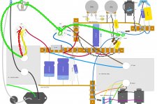
Inspired by Rob Robinette's site and using DIY Layout Creator I came up with a layout for my Two Stroke Amp Head. See the attachment.
Amp Stuff
Software >
DIY Layout Creator : DIY Fever – Building my own guitars, amps and pedals
I plan to use a 12 X 8 X 2 Hammond aluminum chassis.
Hammond 1444-22 - Aluminum Chassis 12x8x2 - Canada
The black and grey twisted pairs represent a shielded cable.
I am using a separate preamp bus and power-amp bus.
The main modifications from the original schematic are:
Mod-1. Added a 470ohm screen resistor to V2 (see forum discussion ), in my schematic this is R15.
Mod-2. Added some SPDT switches to pick 3 of the 4 output transformer impedances.
Mod-3. Based on Uncle Doug's videos, some helpful forum members, and Merlin's book , the 68Kohm grid stopper on V1 should be smaller. Fender amps would have the equivalent of 34Kohm and Merlin suggests that 10Kohm + 680pF capacitor will be quieter. I have not updated the layout yet but I am considering it.
Questions:
What would you change?
The layout is roughly scaled so I think the chassis will be big enough.
How about the tube layout?
The transformers positioning?
The filament wiring?
Thanks
I am building a Two-Stroke based on Dave Hunter's book.
The Tube Amp Network hosts a copy of the layout and the schematic.
http://www.tubeampnetwork.com/wp-content/uploads/2015/07/HUNTER_RevisedLayout.jpg
http://www.tubeampnetwork.com/wp-content/uploads/2015/07/Two_Stroke_TAN_Schematic.jpg
Inspired by Rob Robinette's site and using DIY Layout Creator I came up with a layout for my Two Stroke Amp Head. See the attachment.
Amp Stuff
Software >
DIY Layout Creator : DIY Fever – Building my own guitars, amps and pedals
I plan to use a 12 X 8 X 2 Hammond aluminum chassis.
Hammond 1444-22 - Aluminum Chassis 12x8x2 - Canada
The black and grey twisted pairs represent a shielded cable.
I am using a separate preamp bus and power-amp bus.
The main modifications from the original schematic are:
Mod-1. Added a 470ohm screen resistor to V2 (see forum discussion ), in my schematic this is R15.
Mod-2. Added some SPDT switches to pick 3 of the 4 output transformer impedances.
Mod-3. Based on Uncle Doug's videos, some helpful forum members, and Merlin's book , the 68Kohm grid stopper on V1 should be smaller. Fender amps would have the equivalent of 34Kohm and Merlin suggests that 10Kohm + 680pF capacitor will be quieter. I have not updated the layout yet but I am considering it.
Questions:
What would you change?
The layout is roughly scaled so I think the chassis will be big enough.
How about the tube layout?
The transformers positioning?
The filament wiring?
Thanks
Attachments
Last edited:
Input and output are well separated. Nasty rectifier is kept on the dirty end near the AC inputs. AC transformer alignment is usually tried in both 90 degree alignments to pick the one for less hum before you drill the mount holes. You have the low impedance output tube near the dirty end, the high impedance 12AX7 near the input, that is good.
I don't see the speaker out jack to see if you put a 1000 ohm 3 watt resistor across it to save your transformer if the speaker gets unplugged.
I don't see a 33 pf disk cap across the input to keep RF out. Like the AM radio station in my town that gets into my raw amps.
I don't see the speaker out jack to see if you put a 1000 ohm 3 watt resistor across it to save your transformer if the speaker gets unplugged.
I don't see a 33 pf disk cap across the input to keep RF out. Like the AM radio station in my town that gets into my raw amps.
Last edited:
A steel chassis would certainly be much stronger. But it's a lot harder to work with.
Making something like a cut-out for an IEC power socket is hard enough with hand tools and an aluminium chassis. If it's a steel chassis, it's a right royal pain in the rump! (I wore out many Dremel cutting wheels making one years ago, and don't particularly want to repeat the experience.)
If transformers are going to be mounted in rectangular cutouts, making those in a steel chassis with hand tools is also going to be quite challenging. (I always end up shedding some of my own blood when I work with a steel chassis. With aluminium, usually not.)
That said, this particular Hammond chassis is made from 0.05" (or 1.3 mm) thick aluminium. For those more used to thinking in fractional inches, that's considerably thinner than 1/16", which is already very thin.
I'm baffled, as I remember very well that my aluminium lunch-box when I was a little boy in elementary school was made from much thicker stamped Al sheet, and all it had to withstand was the weight of the two sandwiches my mom made me for lunch.
So, while I've never used this Hammond chassis, the remarkably thin material does give me pause. It suspect it won't cope well with mounting heavy transformers directly on it (a heavy impact from rough handling or dropping the amp might dent the chassis and tear the transformer mounting bolts clear through the thin sheet metal.)
If you mount the transformers on much thicker base plates, and then mount those to the thin aluminium chassis, using large washers to spread the mechanical load, that might do the trick.
-Gnobuddy
A steel chassis would certainly be much stronger. But it's a lot harder to work with.
Unless it's a baking tray or biscuit tin.
 In which case the challenge is to not tear it to bits with the hole saw. (Chassis punch and nibblers are tools I now own).
The lazy/broke student way of reinforcing under-spec chassis is a few off-cuts of softwood or ply.
The main problem with thin materials is the higher risk of cutting through insulation whenever a cable goes through a hole. Use grommets (or dead sockets/pot chassis or....)
Well, here's a STEEL chassis that would fit the bill:
5F1 Chassis Only
It's only $62 and would save a LOT of headache of cutting the holes yourself!
The STEEL is not only going to be MUCH sturdier but much less prone to RF and EMI radiation. The chassis is NOT the place to go cheap.
5F1 Chassis Only
It's only $62 and would save a LOT of headache of cutting the holes yourself!
The STEEL is not only going to be MUCH sturdier but much less prone to RF and EMI radiation. The chassis is NOT the place to go cheap.
RE: steel vs aluminum
very interesting - I hadn't considered the strength aspect
I was more focused on aluminum because:
a) better RF and EMI
b) easier to work with
(one of the D-lab youtube videos mentioned this and watching uncle Doug manhandle blued steel chassis gave me serious pause )
The 5F1 chassis would be $130 CAD ($33 shipping + exchange).
My thoughts so far:
1) based on discussions on another forum I should go up the next size: 16 X 8 X 2. More room, easier to work on. This is a first build, experimental platform, hot-roddish (not pretty) build.
2) with more room, plan to reinforce the transformer mounts. I like the plate idea to spread the load. Naively I guess could make some internal braces under the transformers -- maybe even make a one piece plate + brace.
very interesting - I hadn't considered the strength aspect
I was more focused on aluminum because:
a) better RF and EMI
b) easier to work with
(one of the D-lab youtube videos mentioned this and watching uncle Doug manhandle blued steel chassis gave me serious pause
)The 5F1 chassis would be $130 CAD ($33 shipping + exchange).
My thoughts so far:
1) based on discussions on another forum I should go up the next size: 16 X 8 X 2. More room, easier to work on. This is a first build, experimental platform, hot-roddish (not pretty) build.
2) with more room, plan to reinforce the transformer mounts. I like the plate idea to spread the load. Naively I guess could make some internal braces under the transformers -- maybe even make a one piece plate + brace.
I found a guy on eBay who makes custom aluminum chassis. He is using 2mm aluminum and the quality is very good. I ordered mine custom size without holes but he can punch some holes for you if desired. the JTM box is just an example, you can specify your own size. JTM-45 / 18W Style Chassis w/ Optional IEC Knockout | eBay
user name is synapticamps
user name is synapticamps
This is something our friends south of the border don't usually realize. Things that are massive bargains in America often end up so expensive in Canada that they are not worth buying.The 5F1 chassis would be $130 CAD ($33 shipping + exchange).
The $99 USD Monoprice electric guitar and $200 Monoprice tube guitar amp are good examples - by the time they get here to Canada, the price more than doubles, and at that point, "It's so cheap you must get one!" changes to "Better-manufactured used stuff on Craigslist costs less".
On the chassis, I don't think you will regret having more room, particularly for a first build. Not only will the build be easier, you can also put more space between critical components (like keeping the input jack far from the output transformer wiring), which can help with stability.
As an alternative: I recently went to a local metal shop, and found an offcut of aluminium L-bracket extrusion. About five feet long, the "L" being 1"x3". It cost me less than $15 (CAD), and I figure I can make a reasonable chassis out of two lengths of it, placed edge to edge so that it is a "U" cross section, 6" wide and as long as I want (as long as it's no more than 30", obviously.) You could also bolt both L-extrusions to a flat aluminium plate and make a "U" wider than 6" if you wanted. The "U" could be either 1" deep, or 3" deep. And I'm sure other widths of L-extrusion can be found too.
My calipers say the material is 1/8" thick (0.125", vs 0.05" for the Hammond chassis.) That's two and a half times as thick, at half the price of the Hammond chassis.
But of course it's not pretty like the Hammond, so you'd need to finish any surfaces that are exposed, and you'd need to do a little additional fabricating to join the two L-shaped sections together. I don't know your circumstances, whether that would be easy or hard for you. For a while I lived in a small apartment with no tools, and it would have been impossible for me then.
I've also considered keeping the two sections of L-shaped extrusion separate, but mounting them side-by side in the eventual outer enclosure; For example, one segment carrying the valves, transformers, rear-panel jacks, fuses, IEC inlet, while the other segment is the front panel of the amp and carries pots and knobs and input jacks.
If you have a nearby metal shop, it might be worth paying them a visit to see what might be available to use as an improvised chassis.
Speaking of flat aluminium plate, I found this at my local Home Depot. It comes neatly cut to a rectangle and finished on one side, in 6" and 8" widths, and in 30", 32", and 36" lengths: https://www.homedepot.ca/product/taymor-6-inch-x-32-inch-satin-aluminum-door-kick-plate/1000177295
I totally understand keeping things simple by just getting a nice-looking Hammond chassis, though. It will certainly save lots of time trying to figure out how to put together bits of L-bracket and sheet metal to make a chassis!
-Gnobuddy
I feel for you, I really do. That amazing geographic isolation comes at a high price when it comes to goods from elsewhere.Now double the Canadian prices to get the New Zealand cost.
I hope the incredible natural beauty you have access to in some parts of New Zealand compensates at least to some degree. I would give up many man-made things if I could have a beautiful view of unspoiled nature instead. Goods cost less when I lived in Los Angeles...but the air was brown, the people self-obsessed and unfriendly, and the politics ugly.
-Gnobuddy
I was more focused on aluminum because:
a) better RF and EMI...
So? Millions of fine radios (more sensitive than g-amps) have been built on steel.
Steel is much cheaper in bulk. But more expensive to bend drill punch. Generally "a few" should be in Al. "Thousands" should be steel. Or *buy* from someone already tooled-up in steel.
I should go up the next size: 16 X 8 X 2. More room, easier to work on.
Yes, yes, yes. I have often regretted aiming too small. I can put 5 pounds of stuff in a 5 pound bag. But *changing* one of those stuffs (gone bad, decide to use other-value stuff) is a royal pain.
Rev 2 of schematic and layout
After lots of great feedback from the folks at the Canadian Guitar forum, diyAudio, and TDPI I have:
* a new chassis size and material consideration
* an expanded list of modifications
* new schematic
* new layout
Chassis
Size: Bigger!
Many folks expressed concerns with my proposed 12" x 8" x 2" chassis.
They are right. As much as I love the look of the Greer Mini Chief or Benson Vinny - I should go bigger.
This is my first build -- it's easier to build when you have more room.
This is kind of an experimental, hot-rod, tinkerer build -- it's not meant to look pretty. It's meant to learn from and use as platform for experiments.
So ... I will bump up a size to 16" x 8" x 2" chassis.
Material: Aluminum?
From the link, you'll see the chassis is aluminum.
Aluminum has many advantages for the chassis. It's easier to work, it's non-magnetic, etc.
However, some good folks went a bit further and and checked the manufacturer's specs. The chassis is made out of 1.3 mm or 0.051 inches aluminum. This may be too thin considering the transformers.
My plan is to order the chassis and see.
If it is too flex-y I can stiffen it with some aluminum channels -- as long as I keep that in mind when laying out the amp ;-)
Modifications
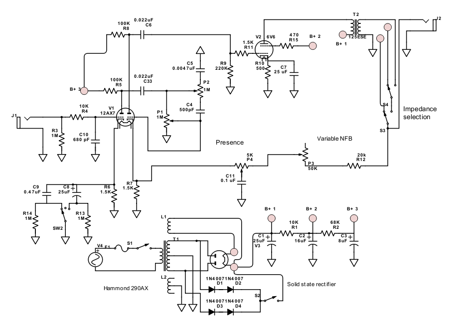
Mod-1. Added a 470Ω screen resistor to V2 (see forum discussion), .
Mod-2. Added some SPDT switches to pick 3 of the 4 output transformer impedances.
Mod-3. Change R4, the 68KΩ grid stopper on V1. I used the Merlin suggested 10KΩ + 680pF capacitor.
new Mod-4. Variable negative feedback
new Mod-5. Presence control.
This was suggested by @mhammer and by watching Uncle Doug: NFB and Presence.
I combined the two. If I understand correctly, the first pot controls the amount negative feedback, and the second will decide how much of the frequency gets rolled off.
new Mod-6. Switchable Solid State Rectifier.
I saw this in a post and post on the Tube Amp Network.
pending Mod-7. @mhammer also suggested a neat mod where instead of voicing switch you replace it with a W-Taper hooked up to the 2 bypass caps so you could vary the amount of bypass.
I don't have the pot now, but there should be plenty of room to replace the switch in the future.
Speaking of W-taper pots, I found an interesting page in Spanish which sounds like it allows you to simulate the pot with regular pots and resistors.
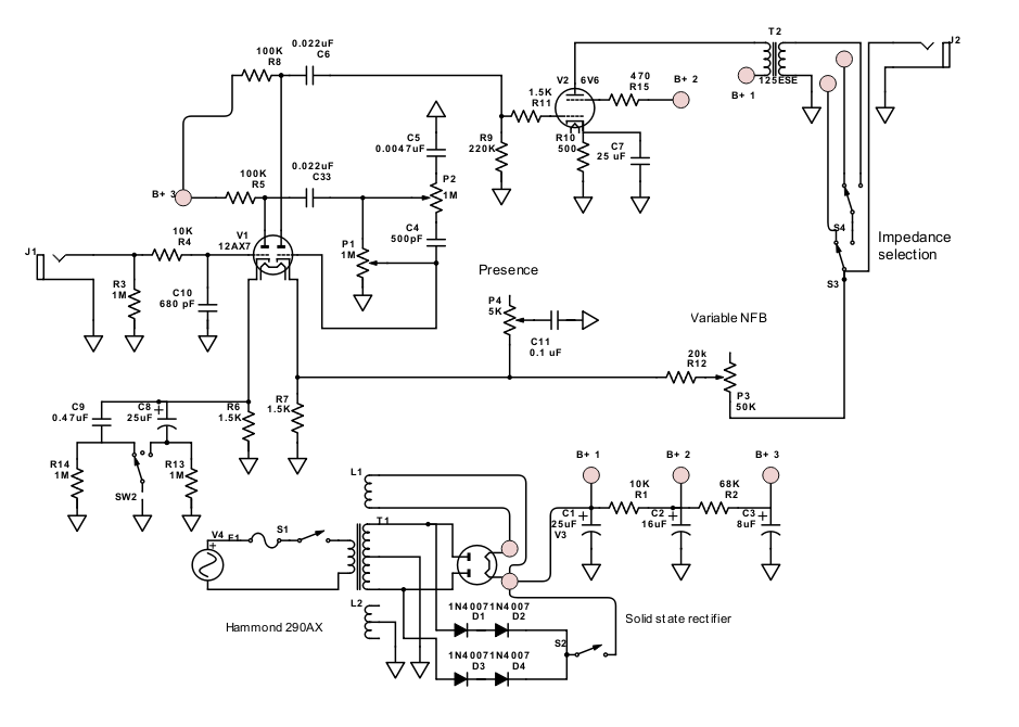
Schematic
Here's the revised schematic using SchemeIt
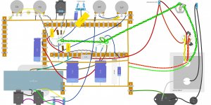
Layout
R.G. Keen's article had some great point-point tips.
Here's the next layout.
Note: I changed the orientation -- you are now looking at the amp from the bottom as opposed to looking through the top.
Why?
* This way seems to match the tube pin number order in the software
* It is what it will look like when I am building the amp

After lots of great feedback from the folks at the Canadian Guitar forum, diyAudio, and TDPI I have:
* a new chassis size and material consideration
* an expanded list of modifications
* new schematic
* new layout
Chassis
Size: Bigger!
Many folks expressed concerns with my proposed 12" x 8" x 2" chassis.
They are right. As much as I love the look of the Greer Mini Chief or Benson Vinny - I should go bigger.
This is my first build -- it's easier to build when you have more room.
This is kind of an experimental, hot-rod, tinkerer build -- it's not meant to look pretty. It's meant to learn from and use as platform for experiments.
So ... I will bump up a size to 16" x 8" x 2" chassis.
Material: Aluminum?
From the link, you'll see the chassis is aluminum.
Aluminum has many advantages for the chassis. It's easier to work, it's non-magnetic, etc.
However, some good folks went a bit further and and checked the manufacturer's specs. The chassis is made out of 1.3 mm or 0.051 inches aluminum. This may be too thin considering the transformers.
My plan is to order the chassis and see.
If it is too flex-y I can stiffen it with some aluminum channels -- as long as I keep that in mind when laying out the amp ;-)
Modifications
Mod-1. Added a 470Ω screen resistor to V2 (see forum discussion), .
Mod-2. Added some SPDT switches to pick 3 of the 4 output transformer impedances.
Mod-3. Change R4, the 68KΩ grid stopper on V1. I used the Merlin suggested 10KΩ + 680pF capacitor.
new Mod-4. Variable negative feedback
new Mod-5. Presence control.
This was suggested by @mhammer and by watching Uncle Doug: NFB and Presence.
I combined the two. If I understand correctly, the first pot controls the amount negative feedback, and the second will decide how much of the frequency gets rolled off.
new Mod-6. Switchable Solid State Rectifier.
I saw this in a post and post on the Tube Amp Network.
pending Mod-7. @mhammer also suggested a neat mod where instead of voicing switch you replace it with a W-Taper hooked up to the 2 bypass caps so you could vary the amount of bypass.
I don't have the pot now, but there should be plenty of room to replace the switch in the future.
Speaking of W-taper pots, I found an interesting page in Spanish which sounds like it allows you to simulate the pot with regular pots and resistors.
Schematic
Here's the revised schematic using SchemeIt
Layout
R.G. Keen's article had some great point-point tips.
Here's the next layout.
Note: I changed the orientation -- you are now looking at the amp from the bottom as opposed to looking through the top.
Why?
* This way seems to match the tube pin number order in the software
* It is what it will look like when I am building the amp
Attachments
This will not work in quite the way you expect. Both R12 and your 50k feedback adjust pot have much bigger resistances than the 5k presence pot. This means that changes to the feedback will also cause changes to the frequency response,a s though you had turned the presence pot; your adjustable negative feedback will turn into (unintentional) adjustable frequency response.new Mod-4. Variable negative feedback
new Mod-5. Presence control.
<snip>
I combined the two. If I understand correctly, the first pot controls the amount negative feedback, and the second will decide how much of the frequency gets rolled off.
At the same time, the frequency response changes that the presence pot was supposed to cause (it boosts treble, creating more "presence") will change; at large resistance settings of the feedback pot, most of the frequency range of the guitar will get boosted, except for deep bass. A presence control normally only boosts mids and highs.
Guitar amps are weird, and it is always possible that you will end up liking this unexpected behaviour. But I wouldn't go drilling holes in the front panel for the variable NFB pot until I was sure I liked it.
Personally, I would also suggest omitting any unnecessary complexity for your first build. S3/S4 is an example - lots of extra wiring to get right, and if you don't get it right, your amp might end up with no load across the output, which kills valve amps (output transformers and sometimes output valves tend to fry if the amp is operated without a load.) I recommend wiring the amp without S3, S4, or the variable NFB, at least at first. Once that's all debugged and working, you can always add the other features.
R.G. Keen has a similar article somewhere, probably buried in his GEO website.an interesting page in Spanish which sounds like it allows you to simulate the pot with regular pots and resistors.
There is a big catch with all of these schemes: once you add the extra taper resistors, the end-to-end resistance of the pot no longer stays constant, but instead, varies drastically as you turn the pot.
For example, R.G. Keen recommends using a taper resistor that's about one-fifth of the value of the pot, to create a simulated audio taper log pot. Let's say we used a 500k pot, and a 100k taper resistor. Now, at one extreme of the pot position, those two resistors appear in parallel. Instead of looking like a 500k load to the preceding valve stage, that "500k" pot now looks like an 83.33k load.
This is okay in some solid-state circuits, when the pot is fed from an op-amp or other very low impedance source. But it can be very bad when the pot is in a valve circuit, and fed from a high impedance such as the anode of a preamp valve.
I agree, and I have been doing this with all my DIY electronics since I was a child. The only exception is when I'm using a solderless breadboard, in which case, you can only see the component side!...looking at the amp from the bottom...it is what it will look like when I am building the amp
-Gnobuddy
This will not work in quite the way you expect. Both R12 and your 50k feedback adjust pot have much bigger resistances than the 5k presence pot. This means that changes to the feedback will also cause changes to the frequency response, as though you had turned the presence pot; your adjustable negative feedback will turn into (unintentional) adjustable frequency response.
doh! I totally messed up transferring the circuit from the fender schematic
does this make more sense?
my naive interpretation is that after the variable feedback resistor (R12 + P3) we are offering variable resistance path for high frequencies to ground instead of contributing to the negative feedback
Personally, I would also suggest omitting any unnecessary complexity for your first build. S3/S4 is an example - lots of extra wiring to get right, and if you don't get it right, your amp might end up with no load across the output, which kills valve amps (output transformers and sometimes output valves tend to fry if the amp is operated without a load.) I recommend wiring the amp without S3, S4, or the variable NFB, at least at first. Once that's all debugged and working, you can always add the other features.
I agree completely. Like we say in the programming world "if you want to make a large program that works, you have to start with a small program that works. if you start with a large program, it might never work"
Once the design is ready, I'll post a list of proposed build steps to get some feedback. The idea is that some of the optional features would be hooked up later after each of the preceding steps is checked.
Since I might paint the chassis I think I will pre-drill the holes for switches and knobs -- in the worse case scenario I might have to put in plugs or dummy knobs but I could live with instead of try to drill new holes in populated and painted chassis.
Has Canada joined the EU?Things that are massive bargains in America often end up so expensive in Canada that they are not worth buying.
Or the Russian Federation?
Last time I checked, Canada and the United States of America were both in America.
As of tariff barriers, ugly as they look, they are starting to be used again, eventually all over the World, unless everybody is happy about losing any Industry related job and becoming a Walmart greeter, Mc D staff or soybean planter and harvester.
Except in China of course, where the exact opposite is happening, straight from the rice paddy to a Factory.
As of Aluminum chassis, 1.3mm is *just* enough , I manufacture my own Guitar amp chassis out of custom made "semi hard" 1.25mm and 1.5mm aluminum sheet with excellent results for 50 years now.
In fact my very first Fender clones in 1969 were C (or U) shaped aluminum sheet, kindly cut and folded by my local galvanized steel stuff fabricator (think cow and pig feeding and drinking trays, restaurant smokestacks, roof rain piping, etc.) , end reinforced with hardwood blocks and drilled with standard drills plus punching socket holes with Greenlee type hand powered punches.
FWIW I STILL have the original ones ... plus my beloved bench hollow riveter ... which I bought 50 years ago to be able to make riveted boards "like Fender did" ....
Still working faithfully, nowadays riveting terminals in chassis and speaker frames and on speaker cones.
Almost forgot: where needed I cut a rectangular piece of aluminum and I rivet it (using this machine) to the main chassis, thus doubling thickness there ... works like a charm.
Of course you can use Pop rivets or screws.
Sadly, the USA is the only country on the continents of North and South America that doesn't have its own name.Last time I checked, Canada and the United States of America were both in America.
Due to this rather remarkable oversight, it borrowed the name of the continent it's on.
No Canadian wants to be associated with the name "America" these days, given the current political regime south of our border, so we're certainly not going to refer to ourselves as "American"!
Speaking of America the continent(s), the two Americas were popularly believed to have been "discovered" by Christopher Columbus, a man who was so utterly lost that he thought he was on the other side of the planet when he made his "discovery".
But instead of being named "Columbia" or perhaps "Christophoria", these two continents were named after Amerigo Vespucci, whose chief contribution seems to have been discovering that Brazil was not actually part of Asia.
However, this is not as unfair as it might seem, because we now have plenty of solid archeological evidence that the Vikings discovered north America about 500 years before Columbus did:
1) Vikings in Canada | Royal Ontario Museum
2)The Viking Explorer Who Beat Columbus to America - HISTORY
And that's not to mention all the Native American peoples who had already been living in both North and South America for thousands of years when Leif Eriksson landed. I guess they just didn't count as far as Columbus was concerned, because their skin wasn't the same colour as his.
Even the Native American peoples don't get the last laugh, though, because it seems still another group of people arrived in what is now Mexico - by boat - as much as 16,000 years ago:
Most archaeologists think the first Americans arrived by boat. Now, they’re beginning to prove it | Science | AAAS
Considering that our species has been around for maybe 250,000 years, I wonder if it is possible that other groups of humans may have made it to the Americas tens of thousands of years before that. We know that the aboriginal people of Australia made it, by sea, to that continent maybe 50,000 years ago ( Aborigines: The First Out of Africa, the First in Asia and Australia - The Atlantic )
So long ocean voyages to distant and isolated lands did occur even that far back. Tropical Central America would have been an ideal place to live for early humans without sophisticated clothing, shelter, or agriculture, so if they did arrive, there is a good chance they successfully lived in, and populated the area.
Many countries in the area are still very poor and the people are at subsistence level, so I doubt there has been much archeological exploration looking for signs of early human habitation.
I've been thinking about something similar. The city I live in used to be mostly industrial at one end and rural (farms) at the other. Now it's rapidly turning into square kilometres of concrete stuffed with ugly blocks of apartments, but traces of the industrial past remain - there is still a metal shop not too far from me....C (or U) shaped aluminum sheet, kindly cut and folded by my local galvanized steel stuff fabricator...
I've bought aluminium offcuts from them in the past, also had them cut sheet Al to size for projects. I haven't asked if they also fold sheet metal to order, but probably they do. I bet it comes out cheaper than those Hammond chassis.
-Gnobuddy
It certainly does. Now R7 keeps the impedance across the presence network from rising above 1.5k, allowing P4/C11 to do their thing.does this make more sense?
The variable NFB pot will still have some effect on the presence control, but now it will be relatively minor, and shouldn't matter at all for a guitar amp.
That's how I see it too, but when in doubt, I draw it up in LTSpice and simulate it...that can give us a more accurate idea than our quick gut-feel estimates.my naive interpretation is that after the variable feedback resistor (R12 + P3) we are offering variable resistance path for high frequencies to ground
The funny thing is that if you implemented this sort of presence control around, say, an op-amp, you would end up with an oscillator. Cutting treble in the feedback causes the open-loop gain to rise at +6 dB/octave, and when this rising response meets the falling open-loop response of the op-amp, there will almost certainly be enough gain and phase shift to cause outright oscillation.
But a valve amp like this usually doesn't have enough open-loop gain, or enough negative feedback, to create oscillation. And so "presence controls" became somewhat common in vintage valve guitar amps.
Exactly!"if you want to make a large program that works, you have to start with a small program that works."
I loved programming when I first got access to computers in the late 1980s. My first programming teacher never said a word about debugging, or taught us anything about writing code that was less likely to be buggy in the first place.
After a few early disasters with Fortran IV (!!!), I taught myself C, and learned to start my programs using lots of stub functions, which often had little more than a "printf();" and a "return(0);" statement in them, and build up the code piece by piece from there.
I don't program much any more - life's too short to spend hours hunting for missing semicolons and mismatched parenthesis!
(But I am coaxing an Arduino into doing some back-flips for me, for an ongoing experimental project I'm working on. It's a fun platform to work with.)
-Gnobuddy
> Christopher Columbus, a man who was so utterly lost that he thought he was on the other side of the planet
Odds are that Chris, an adequate navigator, knew full well he was nowhere near "China". It was hard to get an accurate longitude without a good clock, but you can rough-it by observing solar noon, using the sand-glass to transfer time to night, and comparing star observations to a Portuguese ephemeris. Also by throwing a float behind and timing the run-out to the end of the rope ("log") to get speed and thus distance. He knew he was thousands of miles short of China.
He may have figured the East Indies sprawled much further east than anybody knew, and he was on the east end of the East Indies. But in any case, he knew he had found land unknown to most Europeans, not obviously dominated by any superpower, and thus ripe for exploitation (which he tried, badly).
- Status
- This old topic is closed. If you want to reopen this topic, contact a moderator using the "Report Post" button.
- Home
- Live Sound
- Instruments and Amps
- First crack at P2P layout