I picked up a Teisco Checkmate 20 amp and promptly ruined it.... The reverb was not working, so I decided to feed a signal to the output of the spring tank to see if the recovery circuit was working. It worked fine,(roughly have the original signal strength) so I figured that the tank was bad.
With the signal feeding into the tank output, i had the bright idea to feed the audio signal from the tank input,(output from preamp) back into the main instrument input, to see if the reverb input circuit was working.
The amp promptly oscillated, and blew a fuse. It will blow a fuse immediately if the output transistors are connected. Without them, the tremolo light flashes normally, and voltages seem sane.
I don't have any experience with germanium parts, and the datasheets I find online are vague on pinout, or else I just missed the boat. Usually the case....
Any guidance would be fantastic.
Transistors are 2SB407 Sanyo
Thanks in advance!


Sent from my SAMSUNG-SM-G900A using Tapatalk
With the signal feeding into the tank output, i had the bright idea to feed the audio signal from the tank input,(output from preamp) back into the main instrument input, to see if the reverb input circuit was working.
The amp promptly oscillated, and blew a fuse. It will blow a fuse immediately if the output transistors are connected. Without them, the tremolo light flashes normally, and voltages seem sane.
I don't have any experience with germanium parts, and the datasheets I find online are vague on pinout, or else I just missed the boat. Usually the case....
Any guidance would be fantastic.
Transistors are 2SB407 Sanyo
Thanks in advance!
Sent from my SAMSUNG-SM-G900A using Tapatalk
I used the "diode" setting on my dmm, and I get a diode drop (118 on the meter) between the base-collector and base-emitter junctions. I also get very low 0.3ohm readings across these junctions. What I cannot do is get the transistors to operate by putting the + probe on the emitter and the - probe on the collector, while shorting the base to the collector.
I've verified the test procedure on small signal pnp transistors I had on hand. (I can get them to turn on)
Monkey see monkey do doesn't make me an electronic tech though.... is this a strong enough indication that they are bad, and do the 118 readings correspond to 1.18v and indicate germanium?
Thanks again,
Sent from my SAMSUNG-SM-G900A using Tapatalk
I you can get a datsheet, you can do a Iceo test. Try datasheetcatalog.com first, theirs are more complete than alldata
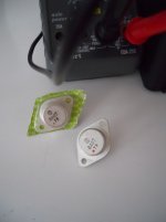
If they are TO3 like in the picture, then collector is case. If you look at the lead side with the long dimension towards you, base is usually on the left, emitter is usually on the right.
Warning, to newbies, voltage over 24 across your heart can stop it. One hand at a time when fooling with voltage on, other in pocket until you have some experience. Use a alligator cliplead on the meter negative. No distractions, kids, wives, cellphones, TV, focus on the job at hand.
Voltage over 1v can burn your fingers to charcoal through metal. No jewelry on hand or neck.
Build a supply about half the Vceo.
put a 47k resistor in series with it.
Connect appropriate polarity to the collector ,from the emitter run through the current function of a DVM before going back to supply. This is the base open test.
Apply voltage (not very long) see what the current is.
Less than the Iceo rating on the datasheet, then try a 10 k resistor.
Less than the rating on the datasheet, it is probably good.
Lots more current, it's blown. True of any transistor.
Good luck. If you had to buy these it would cost more than the amp probably. Geophysics used vacuum tubes and x00:1 transformers to drive solenoids for a decade after germanium was available, before 2n3055 got affordable. They tried germanium early; all that equipment ended up on the boneyard shelf. I worked at a oil exploration lab 74-77.
Last edited:
Thanks indianajo!
I'll check for that datasheet, and do the test.
I've got a 12.7v xfmr, so it'll be easy to run the test.
Thanks for the safety tips! I'm a lineman by trade, and it amazes me all the time how much damage electricity can do in so short a time.
I have a tube amp that runs about 350v, and it's easy to remember safety there. It's too easy to be casual with aluminum caps that go off like bombs with seeming low voltage. (Almost lost an eye one day)
I'll report results as soon as I have them.
Sent from my SAMSUNG-SM-G900A using Tapatalk
I ran the ICEO tests this morning.
ICEO spec is -10 uA
ICEO with 47k resistor -30 mA
ICEO without resistor 7 amps !!
Looks like the CE junction is toast.
I ordered 2 NOS Sanyo off ebay.
I was assuming they were germanium because of the previous "diode" readings, so I ordered germanium.
Is there a way to know otherwise?
The driver transistors give about a 200 on the diode setting, so I was figuring around a 0.2v diode drop.
Sent from my SAMSUNG-SM-G900A using Tapatalk
Incremental update.
I can successfully pass a 1khz signal from the guitar input to the driver transistors and control it with the volume knob.
Hopefully when the new 2sb407's get here on Wed I can solder them in and get back to playing through it!
Sent from my SAMSUNG-SM-G900A using Tapatalk
I can successfully pass a 1khz signal from the guitar input to the driver transistors and control it with the volume knob.
Hopefully when the new 2sb407's get here on Wed I can solder them in and get back to playing through it!
Sent from my SAMSUNG-SM-G900A using Tapatalk
The '118' on a diode range on the DVM means 118 millivolts which is Germanium territory. Try it on silicon and it will be in the 550 to 750 region depending on the devices and the meter test current.
Germanium are inherently 'leaky' but if on an ohms range you are getting very low C to E readings then the transistor is faulty.
I think I have some Germaniums somewhere, if you want confirmation of actual meter readings on them then I can copy them down. Definitely check your ebay ones read in the <200 region from B to E and from B to C when the black meter lead is on the base.
Poynton
I have transistors on the way, are the OC35 better? They are similar to the 407's.
Do output transistors make a difference in sound like some tubes do? (Another rabbit hole...)
Mooly
Thanks for the info.
If it's not much trouble, I would love to see numbers from known good parts.
Sent from my SAMSUNG-SM-G900A using Tapatalk
Last edited:
Next thing we know, you'll be saying you didn't know thermionic valves existed.Very interesting. I didn't know germanium power transistors existed. I only started electronics in the 80s though")
I think germanium power transistors were part of the reason early solid-state amps developed such a poor reputation for reliability.
I used germanium transistors scrounged from old equipment for my first few childhood electronics experiments. The "power" transistors in early transistor radios were good for a whopping few tens of milliwatts of audio power!
-Gnobuddy
Mooly
Thanks for the info.
If it's not much trouble, I would love to see numbers from known good parts.
Here we go
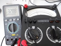
and the devices tested just happened to be First shot shows that the DVM on diode range really is displaying its own test voltage across the terminals. That voltage is read on the AVO as proof.
The meter and its range makes an enormous difference to the readings because of both the test voltage used and the test current that flows. The AVO on low ohms ranges uses a 1.5 volt battery and on high ohms ranges a 15 volt battery.
Code:
[B]Forward biased

      [/B][B]DVM Diode range   DVM Ohms          AVO on low ohms
[/B]B-E   0.153             116               5 ohm
B-C   0.152             115               5 ohm
C-E   2.162             470               2.5k

[B]Reverse biased                            AVO on high ohms
[/B]B-E   Open (3.336)      175k              470k
B-C   Open (3.337)      153k              2.5 meg ohm
C-E   Open (3.090)      1.7k              42k
Attachments
I was assuming they were germanium because of the previous "diode" readings, so I ordered germanium.
Is there a way to know otherwise?
I would have assumed that, too. 'Cause it would be very unusual to find only PNP silicon devices in an amplifier's output.
Best regards!
Thanks Mooly!!!
Nice transistors.
I'll use those numbers as a reference to testing the ones I get next week.
I've never used an AVO, but I have a fluke, cheapy harbor freight and a heathkit vtvm.
Being a newbie, I'm full of questions, so why do you use the different settings to reverse bias the transistors? I'm guessing it's because the 1.5v won't be enough to break them over. If that's the right term.
I'd be interested in those transistors if you want to part with them.
Sent from my SAMSUNG-SM-G900A using Tapatalk
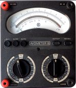
The AVO has very specific ranges and the scale is non linear for resistance measurements. You can see the x1, x100 and X10K ranges on the right hand switch. So you need to use a range that gives readable resolution for the test in hand.
The X1 and X100 ranges use the 1.5 volt battery and so that is the maximum voltage that can appear at the leads, and as you say, it isn't enough to get a reverse biased junction to breakdown. The high ohms range is great for identifying leaky silicon devices that a DVM won't pick up on.
The germaniums I do have are to rare to part with I'm afraid
Attachments
That 15 v test meter Mooly has is rare and expensive. So are the batteries for it. 22 v batteries used to be common but went over $5 apiece when people stopped using them. That is why I suggest you test Iceo with a home built power supply and DVM milliamps scale, which can be built with a $1 surplus wall transformer and $1 in rectifiers, capacitors, and resistor. The 2 v my DVM tests ohms at won't break down a zorked transistor. 12-15 v usually will, and 50-75% of the actual Vceo rating definitely will.
I don't know about the guitar amp world, but I have 3 organs designed 1963-68 with PNP silicon push pull output power amps. TO3 parts on an aluminum plate for a heat sink. PNP power transistors were a lot cheaper than NPN until RCA got the homotaxial process going. But 2n3055 weren't cheap even in 1970. About five hours pay each if I remember right.I would have assumed that, too. 'Cause it would be very unusual to find only PNP silicon devices in an amplifier's output.
Best regards!
Mooly
Thanks for the info. I appreciate the time you've taken to educate me. I didn't figure you wanted to part with them, but it never hurts to ask!
I was happy to find a pair for $20
Indianajo
Thanks for the info too.
I ended up using. 12.6v xfmr---bridge rectifier--dvm--transistor.
This is a great learning experience.
Now I need to wrap my head around the output topology.
Thanks again guys!
Sent from my SAMSUNG-SM-G900A using Tapatalk
Looks like a Darlington pair on the negative side, and a Sziklai pair on the positive side. Basically a way to make two PNP power transistors behave as though one was NPN and the other PNP. Also called a quasi-complimentary output stage.Now I need to wrap my head around the output topology.
In the era before matched complementary output transistors were affordable and available, this assymetrical output stage seems to have been quite common for a while. I've seen them in old Phillips Hi-Fi circuit books, countless Wireless World articles, and a fistful of other electronics books I can't remember.
Here's a decently informative pair of links:
1) Darlington Transistor and the Sziklai Darlington Pair
2) Quasi Complementary Transistor Output | Radio-Electronics.Com
-Gnobuddy
- Status
- This old topic is closed. If you want to reopen this topic, contact a moderator using the "Report Post" button.
- Home
- Live Sound
- Instruments and Amps
- How to test germanium output transistors