Gnobuddy
Wow. That's heavy reading. I've spent most of the day rolling it around my brain.
I see the Sziklai pair on top(positive?), but it doesn't look like a textbook Darlington on the bottom(negative?).
It looks like a common collector feeding a pnp. I read that the CC does not change the phase, is that why it works as a darlington?
I realize we're in thread creep territory here, but I've really gained a lot by ruining these rare expensive transistors...... gotta pay to play!
Sent from my SAMSUNG-SM-G900A using Tapatalk
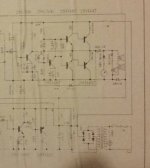
The circuit itself appears incorrect and non conventional.
Firstly, when we have PNP output stages using germaniums it was common (I'd say standard practice) for the amp to have a positive earth. That simply means that if that were the case here then the upper rail (where the fuse is) would be at a negative voltage relative to ground.
The polarity of the caps and the orientation of the electrolytics say this is negative earth.
Odd because that makes the whole circuit behave slightly oddly with regard to signal handling. That's a different issue entirely though.
What is worse, you have two NPN drivers (not possible) and other non marked transistors. The lower driver must be PNP for this to work and in fact the circuit seems to badly show a 2SB487.
(Generally any 2SA or 2SB devices are PNP and 2SC and 2SD are NPN)
So this is not a good example to learn with.
Attachments
Thanks Mooly
I'll do some physical checking, and report back. I don't have the best curcuit tracing skills, but practice is practice right! It makes sense that a npn would be wrong. Everything I was reading, points in that direction.
I have some small npn and pnp pairs, maybe I'll breadboard up a mini version of the drivers and PA, so I can see how it actually functions.
I really do appreciate everyone's help with this. It's fantastic to have a community of people who help and teach each other!
Sent from my SAMSUNG-SM-G900A using Tapatalk
Why don't you simulate it ?
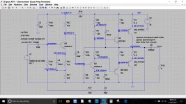
If you are really really interested I'll throw a quick simulation together (I've no Germanium models but that shouldn't matter) and it will show you clearly how it all works.
If you are really really interested I'll throw a quick simulation together (I've no Germanium models but that shouldn't matter) and it will show you clearly how it all works.
Honestly, I wouldn't have the first clue how to do that.
Again if it's no trouble, I would be grateful. Thanks!!!
Sent from my SAMSUNG-SM-G900A using Tapatalk
Again if it's no trouble, I would be grateful. Thanks!!!
Sent from my SAMSUNG-SM-G900A using Tapatalk
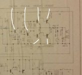
Its no trouble apart from the fact I can't make the values of the passive parts out. Although we could still make a working amp from scratch, it wouldn't be your amp 😉
If you could write them in or write them down then that would be great 🙂
Have to leave it for now but I'll look in later.
If you could write them in or write them down then that would be great 🙂
Have to leave it for now but I'll look in later.
Attachments
Wow thanks!
I'll write in values and hopefully clear this up in my head.
This is awesome.
Sent from my SAMSUNG-SM-G900A using Tapatalk
I'll write in values and hopefully clear this up in my head.
This is awesome.
Sent from my SAMSUNG-SM-G900A using Tapatalk
OK 🙂 and don't worry over the values of the presets and the thermistor, we can find what works when we run the simulation
I'll be back later (hopefully)
I'll be back later (hopefully)
Dear Karl: the bad drawn transistors are marked 2SB, then they must be PNP. 2SA & 2SB were PNP transistors, while 2SC & 2SD were NPN's.
You are wright and I agree with the rest of your comments, except that I saw the 4 combinations of PNP's, NPN's nad grounded + or -. If you respect the wiring, there is no proble.
I saw the old PNP's car radios where there was a special switch to choose ground polarity...Several decades ago
Cordially.
Hi Osvaldo,
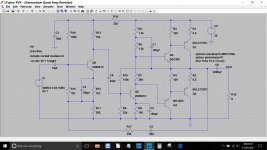
The first two appear to be 2SC536 (marked at top left of diagram) and are NPN. The upper driver is marked as a 2SD187. All the others are PNP.
The first two appear to be 2SC536 (marked at top left of diagram) and are NPN. The upper driver is marked as a 2SD187. All the others are PNP.
I can see between the ground line and the nfb, a 2SB187 clearly.
That's right, but its drawn as an NPN, not a PNP 🙂
Attachments
That's right, but its drawn as an NPN, not a PNP 🙂
Its not really drawn as anything when you blow it up tbh.
Negative ground is fine and proper , since power transistors are connected "upside down" to take care of that.
Top pair is a Sziklai one; bottom pair is a conventional Darlington.
Bottom driver is PNP of course.
If I had that amp on my bench I´d convert it to all silicon and modify bias net, probably to "two diodes + a resistor".
Power output must *certainly* be way above 1 W RMS. What is the supply voltage? Speaker impedance?
Schematic shows 2 in series, so probably 3.2 o 4 ohms each for around 8 ohms nominal total; I´d expect some 15/20W RMS.
That´s not the cheapest amp in the line, since they cared to add a relatively expensive horn and driver.
Mooly
R1=0.5
R2=0.5
R3=100
R4=100
R5=1.2K
R6=? not labeled
R7=0
R8=100
R9=2.2K
R10=series 22k with 100k variable
R11=200
R12=1.2K
R13=15K
R14=22K
R15=12K
R16=150K
R17=22K
R18=6.518 two 8ohm drivers in series, -paralleled- with a 6ohm horn and 5ohm resistor
Q1=2SB407 PNP
Q2=2SB407 PNP
Q3=2SD187 NPN
Q4=2SB187 PNP
Q5=2SD187 NPN
Q6=2SC536 NPN
Thanks so much for your help!!
Last edited:
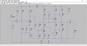
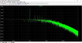
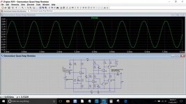
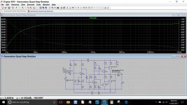
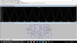
Here is the updated version. R9 looks suspect at 2k2 which would be much to low to work. I've made it 22k. Also tweaked the cap in the feedback network.
You can see how extended the frequency response is although I suspect that the reason is that the simulation is using silicon devices rather than germaniums. The low Ft of the original devices would roll the response off much earlier. If we were fitting silicon replacements then we would tame the response with a small cap to roll the gain off and ensure stability.
I've included the .asc file and models in case you get curious and want to install LTspice 🙂 My signature line tells all 😉
Attachments
Mooly
Thanks again!
I did notice during the short time that I played through this amp, that it was very!! clean. A lot like a fender twin reverb with 6L6's. You were deaf before it really broke up. I has great sensitivity for its low input impedance.
I'll have to have a serious look at ltspice. That's super handy to have reference voltages, and the ability to see what tweaks would do without actually doing them.
I'll have to compare the measurements to actual, and see where it it.
I appreciate your help.
Sent from my SAMSUNG-SM-G900A using Tapatalk
Mooly
I fired up the amp (minus output transistors ) and realized that I had told you 30v supply. That's the PT supply. The DC voltage is 39.7VDC.
Sorry for the misinformation.
Sent from my SAMSUNG-SM-G900A using Tapatalk
I fired up the amp (minus output transistors ) and realized that I had told you 30v supply. That's the PT supply. The DC voltage is 39.7VDC.
Sorry for the misinformation.
Sent from my SAMSUNG-SM-G900A using Tapatalk
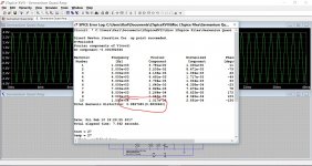
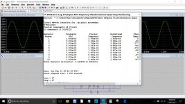
No problem 🙂 its only a click to alter it. R10 and R7 have now be altered to suit. Simulation can tell you so much, you can instantly see the change a cap might make, or how the distortion alters as you change the bias.
I'd really encourage you to try LTspice. It takes minutes to install and the file is ready to click and run.
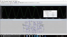
If you compare actual voltages then you will see a difference in the base-emitter voltages of the germaniums. They will be around 0.18 ish compared to 0.6 ish for the silicon. Other than that and it should all agree pretty well.
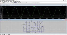
Here is your amp at max output and then at lower amplitude and at 10kHz where we can see the effect of under biasing together with a zoom in of the crossover distortion.
I'd really encourage you to try LTspice. It takes minutes to install and the file is ready to click and run.
If you compare actual voltages then you will see a difference in the base-emitter voltages of the germaniums. They will be around 0.18 ish compared to 0.6 ish for the silicon. Other than that and it should all agree pretty well.
Here is your amp at max output and then at lower amplitude and at 10kHz where we can see the effect of under biasing together with a zoom in of the crossover distortion.
Attachments

- Home
- Live Sound
- Instruments and Amps
- How to test germanium output transistors