Hi all,
I recently acquired a Peavey 5150 (schematic here) from the early 90s in unknown working condition. The seller hadn't powered it up in a few years, but remembers that the volume was low (but present).
Before powering it up, I decided to take a look inside the amp to see if anything obvious jumped out at me. I noticed that the power amp board has had some work done in the past. I contacted the seller, who told me he never sent it to a shop, but did buy it used.
The mods I see are:
I attempted to remove the power amp board to look at its underside, but the power tube sockets appear to be riveted to the chassis. I'd rather not drill these out, if possible.
My questions are:
See attached photos. Thanks for any and all help!
I recently acquired a Peavey 5150 (schematic here) from the early 90s in unknown working condition. The seller hadn't powered it up in a few years, but remembers that the volume was low (but present).
Before powering it up, I decided to take a look inside the amp to see if anything obvious jumped out at me. I noticed that the power amp board has had some work done in the past. I contacted the seller, who told me he never sent it to a shop, but did buy it used.
The mods I see are:
- Some ~68K resistors soldered to some of the tube pins.
- Some board traces cut
- Solder removed from a few joints
I attempted to remove the power amp board to look at its underside, but the power tube sockets appear to be riveted to the chassis. I'd rather not drill these out, if possible.
My questions are:
- Can anyone identify this modification? It looks like a bias mod, but this is where my electronics knowledge breaks down.
- Am I likely OK to power it up (with a bulb limiter) to start checking for issues?
See attached photos. Thanks for any and all help!
Attachments
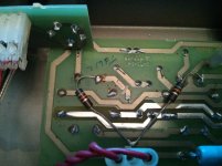
I don't know who did it or why, but it looks like someone just added some grid stopper resistors. I doubt it is a problem.
Yes, the power tube board is riveted in, but rarely needs to come out. The factory schematic includes a layout and all traces are identifiable from the solder side. In fact, when power tubes croak, they often take out a screen resistor. Those resistors are on the underside. I unsolder them from up here. poke them through the holes until they fall down into the chassis. I fish the dead ones out of the chassis. When I install the new resistors, I solder them onto the board up on the solder side. Easy access, and the electrical current doesn't care where the resistor sits.
If you ever actually need to remove that board, you drill out the 8 rivets with a 1/8" drill. Then to re-install, it just takes 8 more new pop rivets, et voila... Please don't make the mistake my friend KB made, he unsoldered all 32 socket pins and pulled the board off them. The problem is trying to get all those pins back into the holes when the board goes back in. (shudder) The whole drilling and riveting thing only takes a couple minutes.
Other than burnt screen resistors from failed tubes, that long blue 400 ohm (390 in some units) resistor should be checked. It is open or it is OK.
So plug the thing in and see what it does.
When I hear a 5150 has low output, my radar aims at Q7. Q7 is on the page with the phase inverter, far right middle. It is a JFET that makes the control signal CLAMP. Now look on the preamp page, center of the right half, near the POST controls. See where CLAMP is with an arrow? That JFET is a mute, it grounds the signal path when channels are switching. If it gets stuck on or is shorted, it will cause sever loss of volume. If I suspect that Q7, I usually just remove it and see if the amp comes alive.
Two more things of note:


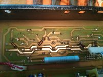
- When reattaching the jumper connectors to the power amp board, I noticed one of the wires had come out of the crimped connector (see photo). I soldered it back on.
- When removing the connector to resolder the loose wire, I noticed a toasty pin under the connector (see other photo). It is still making good connection with its trace, but is a little unnerving.
Grid stoppers promote stability, reduce parasitics and also help prevent blocking distortion. Look it up for better explanations.
Here:
The Valve Wizard
I can't see if your crimped connector housing is burnt from the angle. On the bare board photo on the main board, one pin looks burnt, brown around it. I will say it most likely needs at least to be resoldered. Look at the white nylon housing that plugs onto those pins. Is ther any sign of browning or heat along a couple pins in the middle, notably the browned pin? Sometimes it is prudent to replace teh short cable with soldered on wires between the boards.
Sand it off or otherwise clean its surface. It is badly oxidized, and that pin is carrying the high current of the heater supply to the power tubes. The wires may be intact, but it is the mating surfaces that are compromised. The male pin needs a polish, and look up into the hole in the connector where that pin goes. If you look up the holes, you will see the little crimp pin inside covering the hole so you cannot see all the way through. If that hole has the internal pin surface not fully extended across the hole like the others, it needs attention.
Why not replace the original grid stoppers with the 68k ones. It is bad practise to cut track and solder components on the wrong side of the board. Obviously carried out by an unskilled butcher on a whim. R202, 204, 206 and 208 are 2k2 grid stoppers, just replace them but don't be lazy! Right on the edge with 68k and 220k in series on the grids, they may rise in voltage causing bias runaway.
Peavey and other manufacturers, have problems with 'technicians' unplugging the connectors by pulling the wires. Not a good sign to prompt confidence in the repairer as it causes damage!
Peavey and other manufacturers, have problems with 'technicians' unplugging the connectors by pulling the wires. Not a good sign to prompt confidence in the repairer as it causes damage!
Ok I'll clean off the oxidized pin and make sure it's making good contact with the connector.
On a side note: does anyone know the length and thread count of the mounting machine screws for the preamp board and the preamp tube board? They all seem to be missing on this amp.
On a side note: does anyone know the length and thread count of the mounting machine screws for the preamp board and the preamp tube board? They all seem to be missing on this amp.
Cleaned off the oxidized pin with sandpaper, and checked its continuity through the connector. Looks good.
Connected the amp to a cab and powered it up. Unfortunately, the bulb limiter (60 watt bulb) lit up. The input voltage shows ~121 VAC on the mains cable inside the amp. There is no continuity between the white and black wires of the mains cable, so it looks like the short is somewhere downstream.
How should I go about looking for the short?
Last edited:
I should clarify: the bulb lights when the power switch is flipped on, but the standby switch is still set to standby.
I found this advice on diagnosing issues when the bulb limiter is lit (from here):
* The purpose of the light-bulb is to allow you to keep the amp on - without blowing a fuse - long enough to troubleshoot it. I suggest using a 100 watt incandescent bulb. [If you can't find a 100 watt a 150 is the next best thing. You can not use an LED or fluorescent bulb.]
* Plug the amp in to the light-bulb limiter, turn the amp on in 'standby' mode (if available).
* Switch standby to 'play'. If the lamp lights brightly this indicates a short somewhere in the amp.
* Remove power tubes, one at a time. If the light stays bright, that tube can be put back into the amp. If the light dims, the tube you just removed is shorted. If none of the tubes appears to be shorted, go to the next step.
* Remove all power tubes together. If the light dims, the problem is probably in the bias supply. If the light remains bright, the problem is (probably) a bad rectifier, shorted power transformer, or shorted filter cap - see next step.
* Now switch the amp to standby mode. If the light goes out, the problem is in the filter caps. If the light keeps shining bright, the problem is is the transformer or the rectifier - see next step.
* Remove the rectifier (or disconnect the diodes if it's a hard-wired solid-state rectifier). If the light dims, the rectifier is bad. If the light stays bright, the problem is probably in the power transformer.
Should this list be my next step?
It could be the bulb is too small, or it could be a real problem. Assuming the worst, you need to isolate the problem.
Transformers are the most reliable part of the amp, but we can check it easily anyway. All the secondaries unplug from the main board. Mark where they go and pull them off. Now with only the primary connected, does your bulb still light? Light meaning problems.
With the transformer powered you can verify AC voltages at the secondaries. I think three sets of wires, a pair for high voltage, three for low voltage, and another pair for 6V.
If they are OK, plug one set at a time back onto the board. Does any set cause the bulb to light? If so, which and we can track it down within that subsystem.
what enzo said. By connecting transformer secondaries one branch at a time, the problem can be located pretty easily. If it is in the filament circuit or the power tube circuit, I would swap out for a larger light bulb before condemning the branch. These amps tend to draw more than a few watts while idling.
Thanks all, this is very helpful.
I'll perform the following test:
Note the yellow secondary windings are soldered to the main board, sigh...
JonSnell, how do you recommend I check the bridge rectifier? It is located next to the orange and red secondary connectors (see photo) on the main board, correct?
I'll perform the following test:
- Pull off the secondary connections for the power transformer (circled in green in attached photo)
- Power up in standby mode and check for bulb light
- If no bulb light, replace secondary connections one at a time, checking for bulb light
- If bulb lights with no secondary connections, replace bulb with higher wattage (100W) bulb
- If higher wattage bulb still lights with no secondaries connected, PT is likely faulty
Note the yellow secondary windings are soldered to the main board, sigh...
JonSnell, how do you recommend I check the bridge rectifier? It is located next to the orange and red secondary connectors (see photo) on the main board, correct?
Attachments
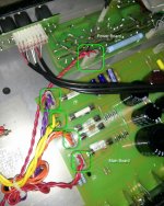
I am not Jon, but I see eight diodes next to the fuses. They are two bridge rectifiers made of individual diodes. Just go down the rows of them and see if any are shorted. Takes a few seconds.
The yellow ones are soldered on, this is common, as the molex connector for that winding is under sized. They burn up and we solder wires directly. So unplug everything else but the yellow wires and see what happens. The yellow would be the heater 6v, you could pull out the white fuse next to them and that opens the 6v circuit.
The yellow ones are soldered on, this is common, as the molex connector for that winding is under sized. They burn up and we solder wires directly. So unplug everything else but the yellow wires and see what happens. The yellow would be the heater 6v, you could pull out the white fuse next to them and that opens the 6v circuit.
Disconnected PT secondary windings from main/power tube boards and ran the above tests with the following results:
It looks like there are at least two issues: a short in the filament circuit and an open secondary winding.
The $300 question: do I need a new power transformer?
- 8 rectifier diodes pass DMM diode test (~.55V drop).
- Bulb limiter does not light brightly, it glows dimly (hurray!).
- Red PT secondary wires (to main board): 320 VAC.
- Orange PT secondary wires (outside two): 35.4 VAC.
- Yellow PT secondary wires: 5.73 VAC.
- Red PT secondary wires (to power tube board): .06VAC (uh-oh!).
- With all connectors unplugged, got no continuity between red wires leading to power tube board.
- Re-soldered yellow PT secondary windings to main board, bulb lights up during power up.
- After removing 10A fuse, bulb glows dimly on power up.
- After reconnecting all connectors (but leaving 10A fuse socket open), bulb glows brightly for a second during power up, then glows dimly.
- After reconnecting all connectors and powering up (still on standby), I hear a click. It seems to be coming from the preamp tube board, but it's hard to say for sure.
It looks like there are at least two issues: a short in the filament circuit and an open secondary winding.
The $300 question: do I need a new power transformer?
No, you don;t need a new transformer, I'll bet my lunch money.
First, that twisted pair of red wires to the power tube board. Look at your schematic, there are no power transformer wires to the power tube board. I think if you follow them back you will find they go to the standby switch. There will be no continuity between them unless you turn on the standby switch, then they will measure shorted together, because that is what the switch does.
By the way, the low voltage at the yellow wires I wager will come back up to 6v once we get the amp off the bulb limiter.
SO I'd agree it looks like you have a short across the heater supply. Let us find out where it is. Put the 10A fuse back in, the bulb glows bright, right? Now disconnect the wires from the main board to the power tube board, the one with the burnt pin we talked about. With the power tube board disconnected, if the bulb no longer goes bright, then the issue is on the power tube board. if it still gets bright, then the issue is on the main board or preamp tube board.
If unhooking the power tube board stops the bulb, then we will look on that board for issues, but first we need to check that jumper wire connector. I wil call it a ribbon even though it is made up of wires. Some work was done on that connector, so we need to make sure all the wires are straight across one to one, and none swap positions on the way across. We also need to make sure no solder blobs have occurred unto the board. With the ribbon off the pow tube board, and of course no tubes in it, measure resistance between pins 2 and 7 of any socket. I expect to see about 200 ohms (R200 and R201 in series) is there?
And on the main board, pull the 10A fuse, and measure between the 6v pins, shorted or not?
If the pow tube board off doesn;t help, then the short is on the main board or preamp board. So at that point, disconnect the ribbons from the main board to the preamp tube board. If the bulb goes dim, then the preamp tube board has a short. Not likely but could happen.
None of the ribbons from mainboard to preamp board should cross one another, all ribbons straight across to the tube board. The other ribbons are to the jack board and to the power tube board. COnsidering one of those to the pow tube board is real short, I don;t think they can be reversed. But do make sure ALL ribbons are on the male pins correctly and not off one pin to the side.
There are several relays in the amp, and I suspect if you hear a click, it is one of those.
Last edited:
Spot on, Enzo, what would I do without you? I got confused by the similar wire color and gauge. At least I confirmed that the standby switch isn't stuck shorted ")
I'll perform your tests and report back. What do you mean by 6V pins? The ones connected to the yellow PT secondary?
I'll perform your tests and report back. What do you mean by 6V pins? The ones connected to the yellow PT secondary?
Last edited:
- Status
- This old topic is closed. If you want to reopen this topic, contact a moderator using the "Report Post" button.
- Home
- Live Sound
- Instruments and Amps
- Need Help Deciphering Peavey 5150 Mod