The ribbon over to the power tubes carries the 6vAC for their heaters. That would be two of the pins in that connector, I forget which, somewhere in the middle of it, see the schematic. I can guarantee one of them is the one that was burnt. SO I was wanting to see if there was a short across the 6v supply on the main board, and those connector pins seemed like a convenient place to test.
I assume your yellow wires are now still connected to the board. Pulling the fuse there opens that circuit. Pulling it stops the bulb glowing, so the short is on the board side of that fuse somewhere. The two 6v pins in that ribbon is one place to check, but if you look at the yellow wires, one side goes on into the board circuits, the other side goes to the fuse. So we could just as well check for a short between the continuous side of the yellow wire and the board end of the empty fuse clip. Electrically that is the same as the pins on the ribbon connector. right?
I have to work at the communication, and break myself of vague references like "the pins". Some of my sentences get a little wordy from spelling out descriptions instead of just saying "them" about something. But sometimes I don;t succeed.
Replaced 10A fuse, pulled ribbon cable from the main board, and bulb glowed dimly during power up. Replacing the ribbon cable (connected to both boards) caused the bulb to glow medium-bright. Only the yellow secondary was connected for this test.
Next step is to check resistance between pins 2 and 7 of power tube sockets (with no tubes installed).
Next step is to check resistance between pins 2 and 7 of power tube sockets (with no tubes installed).
I should work on my clarity as well: by "replacing" in my above comment I mean "reattaching". I am still using the original ribbon cable.
Bulb glows brightly when power board attached to main board (with power tubes and 10A fuse installed), but dimly when power board is disconnected from main board (with 10A fuse installed).
Removed power tubes and disconnected main board from power board. Measured ~200 ohms across heater pins (2 and 7) on all sockets. I also measure ~200 ohms across the heater pins on the ribbon cable when the cable is only connected to the power board.
Is it safe to reconnect the power board to the main board and check for ~6.3 VAC at the filaments? What is the maximum amount of time to leave the amp powered up with no power tubes?
I also noticed that I only have ~.4 Ohms resistance between the two heater pins on the main board (with ribbon cable removed). I'm suspecting the toasty heater pin on the main board (see first picture in post #4), especially since it appears to be continuous with the other heater pin next to it. Shouldn't this low resistance act as a short and cause the bulb to light up, though?
Next step is to pull main board from the chassis and check for solder bridges/other weirdness on the underside of the heater pins.
WAIT, you have been chasing a short to the heaters with the tubes installed all this time? Oh dear, I assumed too much. It is way more likely than the rest of these things that a tube itself is the issue.
Until the earth stops rotating and the sun goes nova. The amp can be powered forever with tubes out. What you DON'T want to do is run the amp with no speaker connected while the tubes are in.
A failed tube can short internally, and also if the center post is broken off a power tube, you can then install the tube in eight different orientations instead of just the one. And only one of those eight will work. The wrong ways in may cases will cause blowing fuses. Any of your power tubes have a snapped off center post? Or looking at them in a row, do all four innards face the same way? Or does one tube have innards facing a different direction?
What is the maximum amount of time to leave the amp powered up with no power tubes?
Until the earth stops rotating and the sun goes nova. The amp can be powered forever with tubes out. What you DON'T want to do is run the amp with no speaker connected while the tubes are in.
A failed tube can short internally, and also if the center post is broken off a power tube, you can then install the tube in eight different orientations instead of just the one. And only one of those eight will work. The wrong ways in may cases will cause blowing fuses. Any of your power tubes have a snapped off center post? Or looking at them in a row, do all four innards face the same way? Or does one tube have innards facing a different direction?
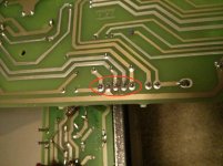
Pulled out the main board. Reflowed the solder at the ribbon cable pins (outlined in red in attached photo), but still have continuity between the two heater pins (3rd and 4th pin from left in attached photo). Ran an exacto knife between the heater pin solder joints to break any microscopic solder bridges, but still measure ~.4 ohms between heater pins.
Am I crazy? Are these pins supposed to be continuous?
Am I crazy? Are these pins supposed to be continuous?
Attachments
Correct, I'd been testing with the preamp and power tubes in. I'll pull the power tubes before testing in the future. All of the power tubes have their center post and keyed feature to ensure proper clocking. Can I check them with a multimeter, besides checking for an open filament?
See attached photo of tubes. They look identical to my eye.
See attached photo of tubes. They look identical to my eye.
Attachments
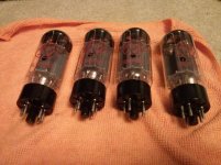
The identical thing was to see if one was cockeyed. If the posts are intact, then they were likely in correct. If I look at a row of tubes and see the innards all facing the same way except one, I can expect that one to be in the socket wrong usually. It wasn't that I expected the insides to actually look different, just looking like they faced different ways in site. In your photo, you have them lying there with pin 1 at top, and inside the tubes, all of them have the hole in the plate facing up. If I had seen four tubes with the hole facing me, I'd be happy, if I had seen four tubes with one facing its hole sideways, I'd suspect the tube was turned in its socket. Enough on that, it does not appear to be your issue here.
Always keep the circuit context in mind. The transformer winding has VERY low resistance. if you measure between those two pins while the transformer wires are on and the fuse is in, then you will get a very low resistance. To do that test you need to pull the fuse. Also, the tubes themselves, the heaters have a low resistance, especially four in parallel, so with the tubes in, we cannot measure for real shorts.
You use the term continuity. That makes me think you are using the diode/continuity test on your meter. You want to use resistance, because the continuity test does not differentiate well between low resistance and a short circuit.
You ran a blade between those two pins, but remember the traces for those pins are more or less parallel across the board to reach the transformer wire connections, they could be shorted together anywhere along that path.
You can check the tubes at their pins with a meter, and it MAY show up a short, but some tube shorts only happen when the tube is hot.
So to get us on track, fire it up without tubes, but all connected to see if we really have a short problem, or if it was bad power tubes all along.
Take a reading of the power trafo filament voltage with ALL of the tubes out of whatever connected board you are testing. If your 6V comes back, this pretty well rules out bad static parts. With near zero current draw, loose connection problems that pass not enough current may show up as good connections.
While the tubes are out, find your way to a tube tester. Any weak or shorted tubes found may end your repair session. Once your excessive current/voltage drop problem is gone, you may still have signal or gain issues. Eliminating all doubt about the glass makes the job so much easier...
While the tubes are out, find your way to a tube tester. Any weak or shorted tubes found may end your repair session. Once your excessive current/voltage drop problem is gone, you may still have signal or gain issues. Eliminating all doubt about the glass makes the job so much easier...
Ok I'll power up with power tubes removed and check for bright bulb state and ~6 VAC on the power tube heaters.
I was using the continuity test, but that still shows resistance on my DMM. The transformer heater secondary has a resistance in the tens of ohms, correct? I get ~.3 ohms when reading across the heater pins on the main board.
I don't have access to a tube tester. Are there any <$100 models that are acceptable (such as this one)?
Pulled power tubes and powered on with main board connected to power tube board. Bulb glows dimly. Reconnected all PT secondaries (still no power tubes in) and powered up again. Bulb flashes brightly, then settles to a dim glow. I measure ~5.2VAC across pins 2 and 7 of the power tubes. I assume this 1.1 VAC drop is due to the bulb limiter.
Looks like I have at least one bad power tube. Should I insert them one at a time to find which one causes the short condition? If only one is bad, can I replace it by itself, or do I need a matched set? I assume I'll have to rebias regardless, correct?
I also noticed that my preamp tubes do not light up. I'll check voltages at the preamp heaters to see if they are in spec.
The 6v winding on the transformer will NOT have tens of ohms resistance, it will have TENTHS of ohms. It is a low number of turns of heavy wire - it is a piece of wire. It will have close to zero ohms resistance.
The bulb flash at first is when the caps and stuff charge up, but it stays dim after power up, so remove the bulb and plug into the wall and now you can see if the 6v comes up to full voltage.
Then go back on the bulb as we continue repair, just in case.
You COULD find the bad tube, and replace only it, but really, it is probably best to put a fresh set in there. A matched set is not required, they are not manufactured with matched sets. The amp will not care. I buy matched sets because the cost is at most a dollar more a tube, and often is no different. Matched tubes will better cancel ripple in the power stage.
Did you TRY using an ohm meter for finding a tube shorted from heater to another element? May not work, but can;t hurt to try. If you find a bad one, try the amp with the remaining three. Not optimal to operate that way, but it won;t hurt it during testing. Just to see if all else works.
The bias is not adjustable on a 5150, unless someone has altered the circuits. The 5150 is biased really cool, and most any set of tubes will work. They are not biased hot like most guys think is required. So instead of 40ma, they are typically idling at somewhere in the 7-15ma range. This results in longer tube life and higher reliability. The power stage is loud and clean, the amp expects to develop its tone in the preamp.
If you look closely at the schematic, the four preamp tubes, the heaters are wired in series mode and are run on DC. Two across +24v and two across -24v. Actually, the middle is not grounded, so they are in fact in series all across the 48v that results from the two suplies. You cannot put just one preamp tube in and have it light up. I don't know where you found 38v, as in between what and what. You have the two 24v supplies, and I assume with no tubes they will rise a bit. So you cannot test voltage at each socket. With tubes out, there ought to be -24v at pin 4 of V3, and +24v at pin 5 of V1. The +24 side has a series resistance. Page 2 of the schematic, right above phase inverter V4, see R47 and R49? Two 22 ohms in parallel for 11 ohms. That drops about 1.65v from the 48v. If they are open, then the preamp tubes all stay dark.
Oh, and tube V numbers are for the schematic, not the chassis. In many amps they are the same, but not this one, the tube order from the end of the chassis is: V1-2-5-3-4. Never assume tubes are numbered in order across a chassis.
Removed bulb limiter from circuit, got ~6.3 VAC on power amp heaters. Reinserted bulb limiter and power tubes, bulb stays lit. A strong signal that I have a bad power tube. None of them showed continuity between the heater pins and any other pin. Ordered a matched set of JJ 6L6GCs, will report back when I install and power up.
Measured 11 ohms across R47 and R49. The 38VDC I reported was between the heater pins on the preamp board (attached to the ribbon cable to the main board).
Measured 11 ohms across R47 and R49. The 38VDC I reported was between the heater pins on the preamp board (attached to the ribbon cable to the main board).
For testing (or 1/2 power output), you can install only a pair of the power tubes to verify operation of the amp and the pair of tubes installed. Be sure to put one tube on each side of the output xfmr primary. You can try to overload the tubes, but they generally don't mind. They can only source so much power before they have no more to give. They won't burn up, they just distort.
COntinuity only tests at low voltage as discussed above.
Hell, on the limiter, I suppose you could plug one power tube in at a time to see which one is the beast. I agree with jeff, you can run on just one pair of tubes for testing.
Hell, on the limiter, I suppose you could plug one power tube in at a time to see which one is the beast. I agree with jeff, you can run on just one pair of tubes for testing.
Installed new power tube set: bulb stays lit after power up, power tubes don't light up.
I don't see any clear issues with the sockets. What else could the issue be? Am I simply drawing enough current with this amp to brightly illuminate the 60W bulb?
I don't see any clear issues with the sockets. What else could the issue be? Am I simply drawing enough current with this amp to brightly illuminate the 60W bulb?
yup. time for a bigger light bulb. You can check reduced voltages at the various points in the amp to verify that power is going as far as it can towards the various destinations, but that amp will most certainly idle at more than 50 watts. I would stick a 100 watt or higher bulb in as a limiter.
Replaced 60W bulb with 250W: bulb does not light when amp is powered up (with power tubes installed). Power amp tubes and preamp tubes light up. Looks like I was just using too small of a bulb. Not so surprising since the 5150 pulls up to 400W. I'll see if I can find a ~100W bulb for the future.
Ran guitar into input: all controls are responsive, but output is scratchy and uneven. Sprayed the pots and will check again after the Deoxit has dried. I'll also try running the signal into the effects return jack to eliminate the power amp as the issue.
Ran guitar into input: all controls are responsive, but output is scratchy and uneven. Sprayed the pots and will check again after the Deoxit has dried. I'll also try running the signal into the effects return jack to eliminate the power amp as the issue.
- Status
- Not open for further replies.
- Home
- Live Sound
- Instruments and Amps
- Need Help Deciphering Peavey 5150 Mod