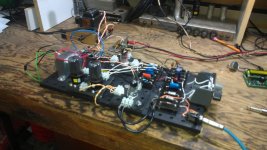
JUST got it working, needed another gain pot before the PI, and removed the tone stack, and WOW it sounds so fine thru a 2x12 cab. Am using both stages of the preamp 12AT7 AND half of the PI 12AX7 for 3 stages of gain (only one input, oh well), and have a Weber 41318 OT (6600/8 ohms) going into a 4 ohm cabinet (means effectively a 3300 ohm primary?). 1 ohm resistors on the 6V6 plates show 44 and 31ma with 345 VDC (less 17.7 VDC at the cathodes), equating to about 14W and 10W each. Pretty unbalanced I know, swapped the tubes with no change.... Have a common RC on both cathodes, might need to separate them to bias the power tubes....but it sound so GOOD. Eyelet boards will go right into a chassis, but I want to play with it first. Built separate preamp and PI boards, so I can maybe build a LTP PI and compare. Is my second amp (the first was a 5F1 Champ). Took a bit longer to build this, but was it worth it! Want to make just a "head" out of it, so I can play with different cabinets. Have some lower power 6W6s and 6K6s to play with as well. And yes the preamp tube is a 12AT7... Gotta go, haven't even put it on the scope yet, or turned it up past 5!
Attachments
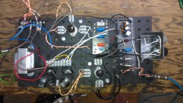
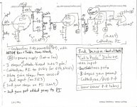
I have a stock Strat and a Tele. This is my first push-pull build, and I looked long and hard at the various designs, don't want a lot of power, but was the next step up from single-ended. I couldn't resist dropping an input to get another preamp gain stage, but used a 12AT7 rather than an AX7 to keep it tame. Also read that the AX7 is best for a PI. Original build (see pic) didn't work at all, so I took out the tone stack and added another vol pot before the PI (see pic). Solved everything, sounds great now. Want to put tone back in it, and learn what went wrong the first time....
- what is wrong with my first design? too much gain? bad stack design?
- can I balance the plate dissipation other than with separate cathode biasing of the the 6V6s? How about the 220K/220K divider resistors?
Thanks all! Jeff
- what is wrong with my first design? too much gain? bad stack design?
- can I balance the plate dissipation other than with separate cathode biasing of the the 6V6s? How about the 220K/220K divider resistors?
Thanks all! Jeff
Attachments
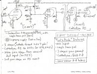
My first design resulted in good tube voltages everywhere BUT pin 1 of the PI (3rd gain stg plate) - was 245V, should have been same as preamp. Cathode (pin 3 was 0). Preamp on scope looked good, but nothing came out the spkrs.... That sent me to the preamp/tone stack, removing it and adding another pot before that PI gain stage.
The first picture, with tone stack, doesn't show any grid leak resistors on stage 3. The volume pot acts as a grid leak for stage 2 (as it does for stage 3 in the second version). Neither version shows a grid leak resistor for the concertina. Nothing else jumps out at me...
Dave-thanks so much for the feedback! This is how I learn. You are right, and someday I "will know better"..... that's what I get for combining multiple designs - you leave stuff out! Wanted to combine the 5E3 dual input stages (ala AA764), but keep the single tone pot from the 5E3. Forgot the grid leak resistor. So backing up (removing tone stack), adding a vol pot before stage 3 gave me the grid leak resistance I needed (to set the input impedance), and I did have a leak resistor on the PI (not shown because my drawing was exact for the preamp, but simplistic for the PI and beyond). I do like the two gain pots, lets me breakup the preamp and power section separately. And do now want to play with a tone stack that cuts treble and bass separately (so will use the AA764 design).
Question - I calculated plate watts with the 1-ohm plate resistor/plate & cathode voltage method. 14 & 10 watts for the 6V6s. This amp is loud! Measured 5.8 VAC across a 4-ohm dummy resistor, calcs to only 8.4 watts. Gotta be more than that?
Question - I calculated plate watts with the 1-ohm plate resistor/plate & cathode voltage method. 14 & 10 watts for the 6V6s. This amp is loud! Measured 5.8 VAC across a 4-ohm dummy resistor, calcs to only 8.4 watts. Gotta be more than that?
Yeah, plate watts don't directly translate to "speaker watts". I'm not sure on the relationship, but certainly there are losses. There are others on the forum who no doubt know a lot about it, hopefully they'll chime in.
I was going to ask earlier but forgot. That seems terribly unbalanced. Are you not using a matched pair of tubes? Are your 1ohm resistors accurate? You might want to not use a shared cathode resistor so you can adjust the bias if your tubes are so badly matched. However, mismatched tubes can add more harmonics and character. Whether it's good character is in the ear of the beholder.")
I was going to ask earlier but forgot. That seems terribly unbalanced. Are you not using a matched pair of tubes? Are your 1ohm resistors accurate? You might want to not use a shared cathode resistor so you can adjust the bias if your tubes are so badly matched. However, mismatched tubes can add more harmonics and character. Whether it's good character is in the ear of the beholder.
Plate dissipation is DC watts, speaker watts have to be AC (only AC goes thru the OT?). As far as my tubes go, I swapped them and no change. Plate, screen and cathode voltages are all the same, so it has to be the grid signals? The paraphase/concertina PI has a 220K/220K voltage divider, I'm gonna put two 250K pots in there and start tweaking. May post/search for a thread on paraphase PI balancing.
The idle dissipation - the no signal, bias setting - is DC. It is a totally separate thing from audio power output. Just as the idle speed of your car engine is separate from the horsepower it produces.
You do not have a 220k-220k voltage divider. A voltage divider has the form of two resistors in series with a voltage applied to the ends, then you take a voltage out at the middle junction and one end. You don't have that here. YOu have two independent grids each with a 220k resistor to ground. They look to be in series, but that is only the drawing style. What if you drew it with each 220k going directly to ground, but at different spots on the page? Wouldn;t look like a divider them.
Changing those 220k values probably won't shift the balance much.
Power off and drain. Measure resistance from the OT primary center tap to each plate - pin 3 of each power tube. Are the resistances close or substantially different. There are a couple ways transformers are wound, and some have different resistance on the winding halves. That becomes a series resistance with the tube currents, and may affect the bias calculations.
If the DC voltages around the power tubes are the same, power up and apply a STEADY signal to the input. Now measure the AC voltage at the grid of each power tube. Is THAT the same for both?
Look at your PI, you have a 56k load for both plate and cathode. How close are those two resistors in value? Note also that your ) phase side is not taken off a 56k, but insatead off the 56k PLUS the 1.5k. That is not much, but it could skew the drive a little.
You could move the cathode drive from the PI to the junction between the 56k and the 1.5k. My amp has 56k + 10k and I'm taking it from the top of the 56k.
As a side note, you should add a large (220k or more) grid stopper to the cathodyne PI. It's important. Read this.
As a side note, you should add a large (220k or more) grid stopper to the cathodyne PI. It's important. Read this.
Great feedback thanks guys!
Enzo: If both 6V6 plate voltages are the same, doesn't that mean the OT windings are the same? And, AC grid input voltages are 35.3/37.5 at max vol, but DC is 13.7/20.0 (respectively). Also, understand the role of the 220Ks now- independant (grid leak?) resistors for the 6V6s? Now, my question about the PI cathode and plate to ground....cathode adds 1500 ohms to its 56K DOOZER says his amp runs the cathode side drive BELOW the 1500, leaving only 56K to ground (like the plate). Will try this! One more thing... doesn't my 1M vol pot to PI pin 2/grid (see previous posted pic) act like a 1M leak and a 1M variable stopper? Thanks again Jeff
Enzo: If both 6V6 plate voltages are the same, doesn't that mean the OT windings are the same? And, AC grid input voltages are 35.3/37.5 at max vol, but DC is 13.7/20.0 (respectively). Also, understand the role of the 220Ks now- independant (grid leak?) resistors for the 6V6s? Now, my question about the PI cathode and plate to ground....cathode adds 1500 ohms to its 56K DOOZER says his amp runs the cathode side drive BELOW the 1500, leaving only 56K to ground (like the plate). Will try this! One more thing... doesn't my 1M vol pot to PI pin 2/grid (see previous posted pic) act like a 1M leak and a 1M variable stopper? Thanks again Jeff
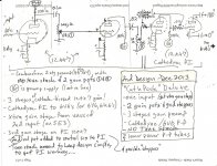
Here's my current build level (Design 3). Tone stack inserted back in. Treble works great, but bass not so much. Will add ground lift switch to insert stack in/out of circuit (thanks ToneLizard). NOTE schematic is exact ONLY up to PI pin 2...remainder is generic.. Thanks
Attachments
Because it could make it sound better. It's bread boarded, why not just try it? It's easy enough. This is the fun of making your own amps.
Did you read the Valve Wizard link I posted earlier? Very good site with lots of useful tips.
Did you read the Valve Wizard link I posted earlier? Very good site with lots of useful tips.
Thanks Doozer! I'm not going to turn this into a final build until I really understand push pull. What I just did was move the cathode drive leg to the other side of the 1500 ohm, putting 56K on it (just like the plate). No change in 6V6 plate currents (31 & 44 mA), or any of the tube plate, screen or cathode voltage. PI DC voltages unchanged (116 pin1,1.6 pin3, 149 pin6, 76 pin8, at idle. BUT.... 6V6 grids another story. Am measuring them before the 1500 ohm stoppers (go to unused pin 6 underneath, only have access to pin6). On the higher wattage tube, DC goes 0 to -16.3 (idle to max), AC goes to 24.7V at max, but peaks at 37V at half vol ("5"). On the low wattage tube, DC peaks at -20.3V at vol "3", then GOES TO ZERO at max vol.... AC is like the other tube: 13V at max vol, peaks at 39V at vol "7". What the #@& is going on? I know nothing about phase inverters (yet), but the amp sounds real good, so I'm not frustrated, just curious.
I just checked them again, this time to the cathode (common point for both tubes, is 17.7VDC above ground). 6V6 'A' grid goes from -17.3 to -40.0 VDC from idle to max vol, and tube 'B' goes from -17.3 to -44VDC (at vol='7'), then drops to -23 at max vol ('10'). numbers relate to my values w/respect to ground (are 17 volts higher)..... I went back to my theory notes, grid needs to stay negative, and the more negative the less current it allow to flow to the plate. Realizing I was reading about small-signal triodes, not phase inverters. Hope someone out there is reading this....... Help!
P.S. I'm using a Fluke mdl 77 DMM....
P.S. I'm using a Fluke mdl 77 DMM....
The (control) grid has to be negative in relation to the cathode. With cathode bias, the grid stays at ground and the cathode is raised above ground, hence the grid becomes negative in relation to the cathode. I'm wondering if your meter is getting confused because of the AC signal.
- Status
- This old topic is closed. If you want to reopen this topic, contact a moderator using the "Report Post" button.
- Home
- Live Sound
- Instruments and Amps
- My breadboard 5E3 deluxe rocks!