You are too kind....if anything is confused its me! I'm going to separate the common cathode bias, and tweak the 6V6s. The amp works, I'll figger out the PI later. I just want to balance the power tubes..... AND figure out how to measure watts to the speaker (simple current x voltage right, with a 1K Hz signal at guitar level....). I get 6.0VAC rms across a 4ohm dummy resistor. E^2/R = 9 watts? No way, the way it cranks my 2x12 cabinet....
Resistive load and inductive load behave differently. The tricky part is that the speaker impedance changes with frequency, hence impedance, not just inductance. Forget the dummy load and check the voltage when driving your speakers. I'm not sure what the nominal frequency is for the speakers to be 4 ohm but 1kHz is typical and might be right. Don't get hung up on watts. It's always surprising how loud low wattage amps can be. Efficient speakers make a huge difference. Also, if you're using your DMM to measure the RMS value at 1kHz it might be reading low. Try dialing back the frequency and see if the voltage goes up.
I used what was said to be a "convention" for speaker wattage: 1KHz into a dummy load (to eliminate the speaker variable), read voltage drop across dummy load and calc power. At least I'd be close! But whats with these speakers and cabinets that have 70-160W ratings? What kind of watts are these?
Back to the unbalanced PI: I've changed the 56K on the leg with the low plate current to 43K, then 68K, with NO change in plate current. So...I'm going to split the common 6V6 cathode R/C and start tweaking there. Oh, and I'll check my brand new Weber OT primary resistances, just to rule that out.....or maybe not.
Back to the unbalanced PI: I've changed the 56K on the leg with the low plate current to 43K, then 68K, with NO change in plate current. So...I'm going to split the common 6V6 cathode R/C and start tweaking there. Oh, and I'll check my brand new Weber OT primary resistances, just to rule that out.....or maybe not.
Unbalance fixed! At least the plate current....separated the common cathode bias into two. Common R was 220 (equiv to 440 per tube?), so ran a 390 to one tube and a 560 to the other. Current was 41/39 mA. Then swapped 'em. Current was 32/35 mA. Increasing resistance raised cathode voltage (above gnd), and lowered plate current. When I balance them closer (32/32), cathode voltages will end up around 20/15. Is this bad? Also, I checked OT primary resistances: the hotter tube was 136.6R, the other 129.6R. Is this normal for an OT? Do the resistance values I used on the cathodes seem out of line? This is where I need to learn about what is normal, within range, or excessive (meaning other things may be wrong). If I swapped the OT primaries, should I expect the other tube to be the "hot" one? Or would this negate (or make worse) an existing imbalance in the PI?
Last edited:
Found the real culprit - tubes not matched.... Put a pair of JJs I had in, everything then started making sense. Went back to a single common cathode R & D, now getting 40 and 39 mA....Whew, now what to do? Figure out how to put both PI signals on my scope, to see it in action when I crank it up!
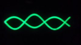
SCOPE SHOTS OF MY CATHODYNE
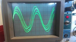
Wasn't too hard, never tried putting two channels into my scope, had to make up another capacitor-protected probe. Took signals (400 Hz off my SigGen) off PI going into the grids of the 6V6s. It looks more gnarly-looking than it sounds, and is a real laser-show when you play guitar thru it! Can anyone out there read what these signals show? Thanks!
Wasn't too hard, never tried putting two channels into my scope, had to make up another capacitor-protected probe. Took signals (400 Hz off my SigGen) off PI going into the grids of the 6V6s. It looks more gnarly-looking than it sounds, and is a real laser-show when you play guitar thru it! Can anyone out there read what these signals show? Thanks!
Attachments
Last edited:
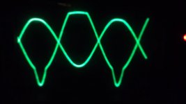
That's nipple distortion from the cathodyne. Didn't you read the valve wizard links I posted? Add 470k grid stopper to the cathodyne and check again.
You know, this whole thread is really bugging me... I want to build my next project (5e3 power amp with my own preamp) so bad! The problem is I need to finish all my other open projects first. Haha...
You know, this whole thread is really bugging me... I want to build my next project (5e3 power amp with my own preamp) so bad! The problem is I need to finish all my other open projects first. Haha...
Thanks Dave. I've had http://www.freewebs.com/valvewizard/cathodyne.html in front of me the whole time. I see the recommendation to use 100K stoppers, but only really needed for Class A (will connect scope to common output signal - see ToneLizard, Tales From The Tone Lounge; Biasing an AA1165 Fender Princeton reverb!, for his scope shots), to see if it the "nipple" (negative gain spike on the anode) made it thru to the 6V6s or not).
100k for the power tubes, but 470k for the pi. I know it cancels in pp but only if the power tubes are perfectly balanced.
Assuming both channels are set to the same V/div, the output of the PI is still very unbalanced.
How much is "very"? Yes I can see some amplitude difference, but how much is too much? And what should I do to correct it? The Cathodyne is supposed to be self-balancing,right?Maybe my scop needs to be calibrated.... Thanks
There's no way for me to tell. I don't know the scale, settings and state of your scope and the schematic is rather incomplete concerning the cathodyne. First thing I would do is to check if indeed the scope is working as it should. Every scope should have a calibration point. A connection with a 1kHz 5V square wave. Connect your probes there and see if you're measuring whats expected.
Where do you take the output from at the cathode side? At the cathode or after the bias resistor?
Where do you take the output from at the cathode side? At the cathode or after the bias resistor?
The imbalance in the first scope capture isn't too bad. It could even be attributed to resistor tolerance (although like funk1980 said, without scale it's impossible to tell). Once the PI starts to be overdriven the imbalance gets worse, which is somewhat unavoidable. In a guitar amp, imbalance like that usually produces some good tones and harmonics. Personally I wouldn't be concerned about it, except for the nipple distortion. Even that can be overlooked if it's not causing any unpleasant tones.
You could move the cathode drive from the PI to the junction between the 56k and the 1.5k. My amp has 56k + 10k and I'm taking it from the top of the 56k.
Hi fellas. I just wanted to reply to my own post here because since getting back into cathodyne analysis for this thread I decided to work up mine in LTSpice. My amp has always had Rk = 10k as I mentioned above, but after thinking about it, roughing a load line, and then simulating it to see, 10k is far from ideal. The amp sounds fine, but the 10k is decreasing the headroom and gain (well, causing more attenuation since cathodyne is less than unity gain). From the simulation I'm seeing that 1.5k is ideal for my B+ of 325V. I will be opening my amp later this week and changing Rk.
It looks like the wave forms are a factor of two apart! I wouldn't call a difference 6dB 'not to bad'. Even for a guitar amp. IMHO a PI with this amount of unbalance would have too much of an effect on the tone. So unless it is a desired effect, I'd look into it.
Mr Funk: I'm building circuits and looking at things on my meter and scope that I never have before, and trying to relate to all the information I can find on the Internet and this forum. Could you explain what "a factor of two" means? I have yet to put any kind of grid stop resistor before my PI, in the hopes of reducing the distortion (and maybe allowing the PI to do its job better?), but plan to and will test different values for their effects. Thanks!
By a factor of two I mean the peaks and valies of one wave are about half the value of the other. Make absolutely sure the voltage/division settings (coarse and fine if separately available) of both channels are set the same. Also check if both probes are measuring the same amount by connecting them to a know source. Once you're sure both channels are equal, you can measure the difference in output from the PI.
A gridstopper is always a good idea. Do you have a schematic of the PI in it's current configuration?
A gridstopper is always a good idea. Do you have a schematic of the PI in it's current configuration?
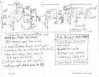
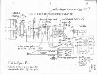
I will check both scope channel calibrations (do have reference on scope). My PI and power sections are exactly like the 5E3 - see pic, except for a 500K pot on PI pin 7 (in series, not to gnd) for grid stop testing. The hand-drawn dwg is my current preamp schematic, showing use of both halves of the 12AX7 for gain on one input, and tone stack from the Champ AA764 (currrently disabled for my testing - lifted gnd). I wanted to make use of the extra 1/2 tube for when I put a LTP or other PI on the breadboard (in place of the Cathodyne), where I would lose the Cathodyne 1/2 tube of gain.
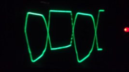
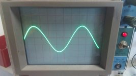
Am currently testing two 6Y6s, need LOW plate & screen voltages (200/135), but get the weird sine wave shown. Only on the 6Y6 plate (not preamp or PI). Clean sine wave is from earlier 6K6 tests. What am I looking at? Thanks!
Am currently testing two 6Y6s, need LOW plate & screen voltages (200/135), but get the weird sine wave shown. Only on the 6Y6 plate (not preamp or PI). Clean sine wave is from earlier 6K6 tests. What am I looking at? Thanks!
Attachments
Quick correction and question: My adjustable 500K grid stopper is not where its indicated on the 5E3 schematic - I have it AFTER the 1meg leak resistor (which I indicate I would replace with a pot - but haven't), directly on pin 7. Question: does it matter if my 500K pot (simple in-series wired) is before or after the 1meg leak resistor? Installed BEFORE may vary the input impedance, but AFTER wouldn't?
Last edited:
You want to place the grid stopper for the split load PI before the 1M resistor. I don't think the nipple distortion is your problem because you are driving a class AB PP section and that valve will most likely be "off", are you seeing any frequency doubling? This is caused by driving the PI too hard via your extra gain stage, I believe the grid stopper will help you with this issue.
Also on another note if you do not have a true rms meter than measuring AC is an educated guess on behalf of the meter.
Also on another note if you do not have a true rms meter than measuring AC is an educated guess on behalf of the meter.
- Status
- Not open for further replies.
- Home
- Live Sound
- Instruments and Amps
- My breadboard 5E3 deluxe rocks!