Dropping lots of voltage from B+ for the screen grid
Hi all,
I was wondering if the experts here had any recommendation on how to provide a more or less stable voltage for the screen grid way below B+ on the plate? Something like Uplate = 320V, Uscreen = 150V. Of course a simple resistor could drop 170V via the screen current but that creates a compression effect when the screen current increases for higher plate / screen currents.
The tube in question here is a 6P15P which has a flimsy screen that shouldn't see more than 150V...
Dropping lots of voltage from B+ for the screen grid
Yeah, thanks for the input!
That would allow a "stiff" / "saggy" switch, with the screens on the PT CT and some smallish RC filter OR the screens supplied from B+ the conventional way with a large resistor and a much more squishy reaction to load.
Would require a 240V CT transformer (120 - 0- 120), though - which seems rather hard to find with at least 3A on the heater winding...
Actually found this post by tubelab that does an excellent job laying out the options: 25W with 2xEL86(6CW5)!
Would require a 240V CT transformer (120 - 0- 120), though - which seems rather hard to find with at least 3A on the heater winding...
Separate transformer for the heater. 240VCT = cheap isolation transformer. Should be available all over the world without costing a bundle.
Most vertical deflection tubes (and a lot of horizontals, too) seem to like about 160-ish on the screen and 320-ish on the plate.
I encountered the same issue with a guitar preamp I designed and built some years ago. A bit of compression is okay for a guitar amp, but I was getting more than I wanted to.<snip>
...how to provide a more or less stable voltage for the screen grid way below B+ on the plate?
<snip>
a simple resistor...creates a compression effect...
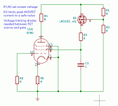
One fix I tried was to wire two resistors in series (a voltage divider) from ground to B+, feed the gate of a small MOSFET from the junction, and feed the pentode screen from the MOSFET source.
Basically, the MOSFET acts as a DC source follower, providing the screen with the current it needs, but with a more-or-less regulated voltage that never strays far from the voltage you set on its gate. (Small changes in Vgs with FET source current will cause slight changes in screen grid voltage, but this will be a small effect compared to not using the MOSFET.)
You need overvoltage protection - in both directions - between MOSFET gate and source, and also a small resistor from MOSFET source to pentode screen, to limit peak startup currents into the screen decoupling capacitor. It also serves to limit peak screen grid current - we don't want any melted screen grids!
The MOSFET has to be able to handle the power dissipation involved: {(B+) - Vscreen} x Iscreen. For a small-signal pentode, screen currents are small, and this will usually turn out to be very little power.
This idea doesn't need a special transformer or power supply, but of course you do waste some power in the MOSFET. It may not matter, particularly for a small-signal pentode.
-Gnobuddy
Attachments
Hi Gnobuddy,
thanks for commenting. Strange - with a small signal Pentode's screen current (<< 1mA) I would have thought a simple voltage divider with a sufficiently large cap to be more than enough! Can you somehow quantify the difference in sag you've achieved?
In my case I'm facing a screen current running from ~4mA to ~15mA at 300V HT. With a voltage divider I'd be burning up some 20W...
I managed to find a small company here in Germany that has offered to make toroidal PTs to my spec - even singles at a very attractive price point. I'll be paying ~ €45.- for 100-0-100V 120mA + 6.3V 4A. That's hardly more than the price for off-the-shelf 250+ V toroidals...
Cheers,
Tom
It might very well be, depending on how many volts of sag you want. (But beware of the "large cap" - more on that in a moment.)Thomas Schwarz said:...with a small signal Pentode's screen current (<< 1mA) I would have thought a simple voltage divider with a sufficiently large cap to be more than enough!
The relevant parameter for the screen voltage "sag" is the Thevenin source impedance of the potential divider, which equals the value of R1 and R2 in parallel, i.e. R_Thevenin=R1xR2/(R1+R2).
It's been a few years, but IIRC, I had a pentode supply voltage in the vicinity of 150 volts, and the actual screen voltage was, let's say, 75 volts (it might have been less, I forget the exact value I ended up using.)
Let's say we decided to use two 100k resistors in series to make a voltage divider, providing 75 volts at the junction when unloaded.
However, the Thevenin (source) impedance of the voltage divider is 50k (the parallel resistance of two 100k resistors). If the screen current of the small signal pentode changes by 1 mA, the voltage at the junction drops by 50 volts! That is a lot of sag, especially if the initial voltage was only 75 volts!
You could instead use two 10k resistors to make the voltage divider, giving you a 5k source impedance, and therefore a probably negligible 5 volts of sag at the screen grid (for a 1 mA change in screen current). However, the two 10k resistors now draw 7.5 mA of current from the 150 V supply, and dissipate over a watt between them.
While a watt of dissipation isn't all that much, having the screen grid bias resistors draw an order of magnitude more current than the anode (plate) resistor is a little annoying. At least to my picky brain.
On the subject of using a bigger cap in conjunction with a voltage divider, keep in mind that using a bigger cap only changes the time constant of the sag, not the total amount of sag after a sufficiently long amount of time. Because the DC source impedance of the voltage divider isn't changed by the addition of a capacitor, there will still be lots of sag if the pentode is overdriven for a long enough time period.
In the case of a guitar amp, if you use a very big screen grid decoupling cap, and the guitarist overdrives the pentode continuously for many seconds (say during a heavily overdriven guitar solo, or by passionate chord strumming through an entire verse), she will then drag the screen grid voltage lower and lower and lower throughout the solo or verse, gradually choking down guitar volume and altering the amount of overdrive, as though someone were twisting gain and volume knobs slowly.
With guitar amps I've found it a surprisingly good rule of thumb to never use a bigger capacitor than absolutely essential, in any location where the actual guitar signal is affected. Big caps tend to lead to excessive bandwidth, excessive bass, and all sorts of odd misbehaviour.
I have a little experience building and testing out a few small-signal pentode gain stages in guitar amps, and I found that it was definitely possible to have a screen decoupling cap that was too big. This produces a very spongy, compressed sounding guitar amp that responds very slowly to the guitar, like a low-quality compressor set with a too-long decay time. It might be suitable for some types of music (slow blues solos, say), but is very poorly suited to fast guitar playing.
At the other extreme, if you use a very small screen decoupling cap, you start to reduce bass response, and get a quicker sag and recovery. The quicker sag/recovery makes it possible to play the guitar at higher tempos without the amplifier misbehaving. And the reduced bass response is usually a good thing too - in a recording studio, guitars are typically high-passed at 300 Hz or more, to remove "mud" and keep the guitars from treading on the territory of the bass and drums.
Power supply filter caps (which aren't in the signal path) are an exception - I like big caps there. Some guitarists claim small filter caps result in lots of intermodulation distortion (between the guitar signal and 120 Hz ripple) that they like. I don't agree - IMO, the only thing you get from too-small B+ filter caps is too much hum.
Sure. It depends on the transconductance (gm) of the FET you selected, at the operating point you chose.Thomas Schwarz said:Can you somehow quantify the difference in sag you've achieved?
Let's look at an LND150 MOSFET as an example. The manufacturer's datasheet doesn't even quote a transconductance (unless I missed it), but data sheet graphs show drain current dropping by about 1 mA when Vgs changes from 0 volts to (-0.5 volts).
So if we run the pentode's screen grid current through this MOSFET, and the screen current changes by 1 mA, the MOSFET will require about a 0.5 volt change in Vgs in order to accomodate the change in screen current.
Since the MOSFET gate is held at a steady voltage by the potential divider, it's source voltage will drop by 0.5 volts as the screen current increases. If the screen grid were connected directly to the FET source, the "sag" voltage would be 0.5 volts.
This is actually too little for my purposes, which is one reason why my schematic showed an additional resistor (R3) beween MOSFET source and screen grid, to re-introduce the desired amount of voltage sag. R3 also protects the MOSFET from excessive peak currents.
Incidentally, since gate current is virtually zero, we could use a pair of 1 Meg resistors for the voltage divider, and still get a very "stiff" screen grid voltage, if that was what was wanted. And the voltage divider would only draw 75uA from the 150V rail, entirely negligible by any reasonable standard.
Heck, you could use a pair of 10 Meg resistors, if you had those in your parts box, reducing current draw of the divider to 7.5 uA.
In this example, power dissipation in the LND150 would be only 75mW at 1 mA screen current, 150 mW at 2 mA, and 225 mA at 3 mA.
I like to be conservative and keep these little TO-92 devices at no more than 300 mW total dissipation, which is sufficient to support up to 4 mA of screen current in this particular application. Way more than needed.
And if you used the MOSFET idea, the FET would only dissipate (15 mA) x (170 V), or 2.55 watts worst-case.Thomas Schwarz said:...screen current running from ~4mA to ~15mA at 300V HT. With a voltage divider I'd be burning up some 20W...
Clearly an LND150 wouldn't do the job here, but a small power MOSFET with a little clip-on heatsink could do the job. I would use a device which is fully encapsulated in plastic, so the heatsink doesn't end up with dangerous voltages on it, waiting to shock an unwary finger.
You could even put a resistor between B+ and the FET *drain*, to drop some of the voltage across itself, reducing power dissipation in the FET. Size the resistor so that the FET still has enough Vds to operate properly, even at peak screen current.
In one of my experimental guitar amps, I started with a transformer that had an end-to-end voltage rating of, I think 60 volts RMS. I used simple diode-and-capacitor voltage-multiplier circuits to generate a few milliamps at several different B+ voltages.
A simple half-wave rectifier produced around 85 volts DC, a voltage doubler around 170 volts, a tripler around 250 volts, and a quadrupler around 320 volts.
I fed the triode stages in my preamp from the 320 V rail, and the pentode stages from the 170 V rail.
The power amp was only about 2 watts using a pair of tiny power pentodes from the "tube radio" era, and IIRC I ran those from the 250 volt rail, with a 22.5k primary output transformer.
Heaters were all powered from a $4 thrift-store 8.2 volts Sony DC switching power supply ("wall wart"), with a suitable-value power resistor inserted in series to drop heater voltage to 6.3 V DC.
-Gnobuddy
Hi Gnobuddy,
First of all, thank you so much for your very thorough answer!
After reading your comments I looked up the EF80's datasheet - which I clearly should have done before posting my previous remark. I was very surprised to find that this pentode istn't actually so "small signal" at all and draws 3+ mA at 75V Ug2 and Ug1 = 0V (https://frank.pocnet.net/sheets/084/e/EF80.pdf) ! I had something like an EF86 preamp first stage in mind (0.1 mA Ig2).
So a power FET with the voltage fixed from an array of zeners (amplified zener diode) seems to be the way to go - maybe even if a suitable lower voltage PT tap were actually available. A stiff variable screen supply looks like a very attractive way to power-scale the amp ...
Cheers,
Tom
First of all, thank you so much for your very thorough answer!
...
It's been a few years, but IIRC, I had a pentode supply voltage in the vicinity of 150 volts, and the actual screen voltage was, let's say, 75 volts (it might have been less, I forget the exact value I ended up using.)
Let's say we decided to use two 100k resistors in series to make a voltage divider, providing 75 volts at the junction when unloaded.
However, the Thevenin (source) impedance of the voltage divider is 50k (the parallel resistance of two 100k resistors). If the screen current of the small signal pentode changes by 1 mA, the voltage at the junction drops by 50 volts! That is a lot of sag, especially if the initial voltage was only 75 volts!
...
After reading your comments I looked up the EF80's datasheet - which I clearly should have done before posting my previous remark. I was very surprised to find that this pentode istn't actually so "small signal" at all and draws 3+ mA at 75V Ug2 and Ug1 = 0V (https://frank.pocnet.net/sheets/084/e/EF80.pdf) ! I had something like an EF86 preamp first stage in mind (0.1 mA Ig2).
...
I have a little experience building and testing out a few small-signal pentode gain stages in guitar amps, and I found that it was definitely possible to have a screen decoupling cap that was too big. This produces a very spongy, compressed sounding guitar amp that responds very slowly to the guitar, like a low-quality compressor set with a too-long decay time. It might be suitable for some types of music (slow blues solos, say), but is very poorly suited to fast guitar playing
...
So a power FET with the voltage fixed from an array of zeners (amplified zener diode) seems to be the way to go - maybe even if a suitable lower voltage PT tap were actually available. A stiff variable screen supply looks like a very attractive way to power-scale the amp ...
Cheers,
Tom
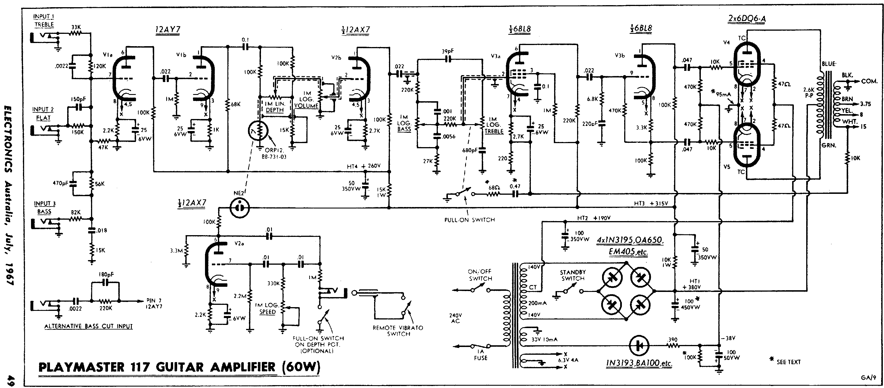
Just in case I'm not the only one that didn't think of using the CT for low-voltage screen supply - I've found this schematic that demonstrates exactly that - incl. the fact that a separate rectifier for the screen isn't required...
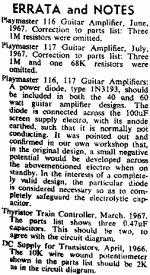
Attached the complete article and errata/notes on this amplifier. A diode across the 100 uF screen supply capacitor was recommended to prevent a negative voltage developing over that capacitor when the amplifier is in stand-by mode.
Philips used the CT for screen supply in some of their PA amplifiers, like the EL6426.
Attachments
That would allow a "stiff" / "saggy" switch, with the screens on the PT CT and some smallish RC filter OR the screens supplied from B+ the conventional way with a large resistor and a much more squishy reaction to load.
Several years ago I experimented with a circuit I called the sagulator. Instead of a stiff / saggy switch, I had a pot that went from stiff to limp. I used the circuit's output to feed one or more stages in the front end of the amp, the whole preamp, or the screen grid of a pentode somewhere in the chain, often the input or second stage, as high gain (around 1000X) pentodes are usually too microphonic to be the input stage.
The circuit was similar to the diagram in post #2188. I put R3 in the drain of the mosfet and sized it so that the output stayed constant until the load current got into the "damage" region at which point the drain voltage dropped below the gate causing the circuit to drop out of "regulation." As stated, gate protection is required. One end of a pot was tied to the junction of R1 and R2 with the wiper going to the mosfet's gate. The other end of the pot goes to a voltage source that drops when the amp is driven. This can be several places.
In a small amp that will be driven hard, hard enough to blow screen grids, I use a large enough screen grid resistor to put the screen at max rated dissipation when making clipped square waves, and tie the screen side of the resistor to the end of the pot.
In a more mild mannered amp, I used a resistive divider from B+ like R1 and R2, except that R2 is the LDR part of a photoresistive coupler like a Vactrol. The LED in the Vactrol can be driven by any signal that varies like the cathode of the output tube.
Some resistor value tweaking will be needed to keep the sagulator output voltage constant as the pot is turned.
Enclosed is the schematic for an amp I developed during the active HBAC competition. It just squeaked in under $100 at the time.
The "too many diodes" power supply is both a full wave bridge and a full wave voltage doubler. The power transformer is an ordinary isolation transformer with a single 120 volt secondary. It was chosen for cost reasons. A dual 120 volt secondary transformer with the secondaries in series would make the power supply simpler, much like the one in the Philips schematic.
Either way you get about 160 - 170 volts and 320 - 335 volts from the supply. The 160 volt source feeds the screen grids of the output tubes and powers the heaters. The 320 volt source feeds the output tube plates and the entire preamp.
The output tubes are 45B5 / UL84's which are 45 volt 100 mA versions of the 6CW5 / EL86. The preamp tubes are 26AQ8 / UCC85's.
Ignore the mosfets in the cathodes of the preamp tubes. They were for an early version of the sag circuit which failed. The preamp had far too much gain, so one of the UCC85's was eliminated and the power supply was revised to feed unfiltered but rectified AC to the heaters making live easier on the power transformer. This added yet another diode to the power supply, but diodes are cheap.
This amp made about 20 watts when using a cheap power (mains) toroid for the OPT. I got about 25 watts with a real 3300 ohm OPT, but that didn't fit the challenge budget. I still have it, but prefer the little 4 tube HBAC amp for daily use. It's 4 watts is loud enough.
Attachments
You're very welcome! In our new Dark Ages of "flat-earthers" and "anti-vaxxers", it's a huge relief to talk about something as real and BS-free as an electronic circuit.First of all, thank you so much for your very thorough answer!
")
No worries at all. Truthfully, I wanted to draw a schematic for you, so I fired up Kicad and grabbed the first pentode symbol I found in it's library. That just happened to be an EF80!After reading your comments I looked up the EF80's datasheet - which I clearly should have done before posting my previous remark.
In the guitar amps I built, the pentodes I used were variously 6AK5, 6AG5, and the pentode section of a 6JW8. At the time, all three of these were available for just $1 USD each. No pricey EF86s for me.
Well, it's certainly one way to go.So a power FET with the voltage fixed from an array of zeners (amplified zener diode) seems to be the way to go -
Most guitar players seem to like at least some sag, to "round off the edges" of the sharp transient that starts off every note played on a guitar. If some pentode sag is wanted, a well regulated screen voltage might not be the best option.
As George alluded to, a lot of output tubes in guitar amps die because of too much screen grid dissipation. Sooner or later a guitar amp will be mercilessly overdriven, screen current will soar, and if you don't plan for this, the output tubes will die a fiery death.
Which is why tube guitar amp designers found out, decades ago, that inserting a resistor in series, sized to keep the screens from overheating, should be considered mandatory insurance. Those designers who failed to do this, created unreliable products that failed in use.
Can you imagine a guitar hero playing rock guitar in front of 10,000 people, and suddenly having his guitar amp die in a shower of sparks just as his loud and impassioned guitar solo is reaching its climax?
...replace R1,R2 with a potentiometer, and you can dial up any screen voltage you want, between 0 volts and B+...A stiff variable screen supply looks like a very attractive way to power-scale the amp ...
More practically, stick a properly sized pot between R1 and R2 so you can dial up a useful range of screen voltages, neither uselessly low, or uselessly high.
The screen voltage isn't actually regulated in this case (it will track variations in B+), but for a guitar amp, do you really need a mathematically exact regulated screen voltage? Most probably not...
By the way, potentiometers have maximum voltage ratings, and smaller pots invariably have smaller voltage ratings, so do keep that in mind. Also, this is one application where I would choose a plastic-shaft potentiometer over a metal-shaft one, simply for the increased electrical creepage distance between dangerous voltages and your fingertips!
I don't think you mentioned what the amplifier you're thinking about is intended for. Guitar? Something else?
-Gnobuddy
Can you imagine a guitar hero playing rock guitar in front of 10,000 people, and suddenly having his guitar amp die in a shower of sparks just as his loud and impassioned guitar solo is reaching its climax? -Gnobuddy
The Ampeg SVT is a popular bass guitar amp. The new ones are solid state, but the "real" SVT had 6 X 6550's and made a very real 300 watts or more. Unfortunately for Ampeg, there was a first gen SVT which often went down in flames. It used 6 X 6146 RF transmitting tubes and tried to make 300 watts. The 6146 should be treated like a modern sweep tube as far as the screen grid is concerned. If properly fed, the 6146 can crank out 75+ watts per pair even in a bass amp. Ampeg overfed the screens and poof happened.
The most famous flameout was at the infamous Rolling Stones concert at Altamont in 1969 where one of the 6146 based SVT's caught fire. Some unrelated murderous activity also occurred at that show, making the flaming amp or amps a minor event. This wasn't just 10,000 people. Estimates put the crowd at well over 100,000 and parts of the event was televised.
Ampeg blamed it on an incorrect setting of the line voltage switch. Yeah, right, like an amp set on 230 volts is even going to work on 120 volt power. Several other 6146 based SVT's flamed out, and the amps were all switched over to 6550's within the first year.
The 6146 has been regarded as a poor choice for audio ever since, but that is unfounded. This subject pops up here every few years.
6159 for SE Power amp
6146W Power Amplifier. Please help!
8552 finals ?
That story was in the back of my mind. It's probably the most notorious case of an imperfectly designed tube amp failing during a live performance, though the tragedy of the four deaths and multiple injuries to people in the crowd completely overshadowed it, as was entirely appropriate.Tubelab_com said:...Ampeg SVT...Altamont...
Unfortunately, music festivals continue to suffer from violence, and violence against women, in particular, tends to be overlooked and under-reported. For instance: Sexual Harassment at Music Festivals Is An Ongoing Problem - FLARE
-Gnobuddy
They got so out of hand in general that the last big festival that I attended was Lollapalooza 96 in West Palm Beach Florida. This was back when Lolla was a touring festival that ran for a whole day on three stages at each stop. The lineup was as diverse as the crowd. Metallica, Soundgarden, Rancid and the Ramones were all in the same show. The punkers played in the afternoon heat and the loud rock / metal came after dark.
There I got to watch a Sovtek MIG 50 go down in flames. Yes, some Russian made guitar amps were sold in the US under the Sovtek brand. They weren't around for long, so I don't know if they all flamed out, or this was a one off crash landing.
There I got to watch a Sovtek MIG 50 go down in flames. Yes, some Russian made guitar amps were sold in the US under the Sovtek brand. They weren't around for long, so I don't know if they all flamed out, or this was a one off crash landing.
Years ago I made it under $100, I think the chassis was not included, made a 12AQ5 (7 pin 6V6) Push Pull Harvard. I sourced most of the parts from one vendor as additional shipping charges account for real money even if it was not included in the $100. Did it again this time a single ended amp using a 12V6 but including chassis.

Did not include the 12V laptop supply, I usually found them in thrift stores for $2-3. Probably add another $12 if you were to buy one new. The other thing about using a high voltage module is it is a lightweight amp and if you have a light cabinet (pine, weigh the wood in your hands, some pieces applicably lighter).
It was a dumb thing going through the exercise but I was curious.
https://www.tubesandmore.com/products/tagboard-300mm-x-56mm-2-x-28-tags $9.95
https://www.tubesandmore.com/products/vacuum-tube-12v6gt-tetrode-beam-power $6.90
https://www.tubesandmore.com/products/vacuum-tube-12ax7-ecc83-jj-electronics $13.25
https://www.tubesandmore.com/products/transformer-output-8-w-single-ended $15.50
https://www.tubesandmore.com/products/socket-belton-micalex-8-pin-octal-mip $3.50
https://www.tubesandmore.com/products/socket-belton-9-pin-miniature-top-mount $2.95
https://www.tubesandmore.com/products/14-jack-switchcraft-mono-shunt-tip $2.35 x2
https://www.tubesandmore.com/products/14-plug-switchcraft-cable-mount $3.15
https://www.tubesandmore.com/products/chassis-box-hammond-aluminum-8-x-4-x-2 $13.28
https://www.tubesandmore.com/products/receptacle-iec-c14-power-cord-3-prong $1.95
https://www.tubesandmore.com/products/fuse-holder-fender-3ag-type $2.50
https://www.tubesandmore.com/products/knob-chicken-head-set-screw-brass-inset $1.25 x 4
https://www.tubesandmore.com/products/potentiometer-alpha-linear-solid-shaft
250k $1.55 x3 1M $1.55 x1
https://www.tubesandmore.com/products/capacitor-450v-axial-lead-electrolytic 22uF $2.20 x3
https://www.tubesandmore.com/products/power-jack-dc-panel-mount-55mm-external-21mm-internal $0.75
https://www.tubesandmore.com/products/switch-carling-mini-toggle-spdt-2-position-solder-lugs $2.75 x2
https://www.tubesandmore.com/products/resistors-2-watt-metal-oxide-power
470R $2.85
39R $2.85
https://www.tubesandmore.com/products/resistors-1-watt-metal-oxide-power-5-tolerance
1M $2.30
33k
75k
1.5k
4.7k
10k
47R
2.7k
https://www.tubesandmore.com/products/capacitor-500v-silver-mica-5 500pF $0.84
https://www.tubesandmore.com/products/capacitor-630v-metal-film-tubular
0.022 $0.46 x2
4.7n $0.60
0.082u $0.61
0.047u $0.74
https://www.tubesandmore.com/products/diode-general-purpose-rectifier-1a-1n400x 1N4007 $0.25 x2
https://www.tubesandmore.com/products/capacitor-illinois-50v-axial-lead-electrolytic 22uF $0.60 x 3
https://www.tubesandmore.com/products/wire-22-awg-stranded-core-pvc-600v-variety-pack $11.50
https://www.ebay.ca/itm/144357187611?hash=item219c5be01b:g:QScAAOSwroVhsdRT $6.01
$149.33
Only need one diode to protect against the wrong polarity voltage adapter applied. I was not thinking low voltage and selected a 1N4007, not going to bother with getting a proper one, will not change the cost much. The BF stack is worth the extra money as compared to a basic tone control, another $15 for it and the switch that gets you a more Marshall response.
- Home
- Live Sound
- Instruments and Amps
- The Hundred-Buck Amp Challenge