Interesting! Is that by any chance Roly Roeper's design, from the Aussie Guitar Gearheads forum? I recall that he once posted an LTSpice simulation of a circuit that used controlled bootstrapping (small amounts of positive feedback) to vary the effective capacitance seen by the guitar pickup.
-Gnobuddy
Not really - the idea is much older and dates back to the VOX WahWah Pedal in the sixties. Let me look for a simulation....
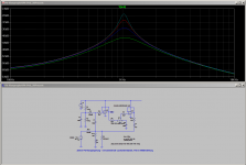
This is a simulation using one OPA as input buffer and the second OPA for variable cap tone control. Frequency response is shown with the pot in mid position.
The practical circuit is fitted with JFET-buffers instead of OPA yielding good noise performance with low power consumption.
The practical circuit is fitted with JFET-buffers instead of OPA yielding good noise performance with low power consumption.
Attachments
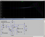
Now that Voltwide reminded me of the variable capacitance technique, I couldn't resist quickly throwing a circuit together in LTSpice.
Roly Roeper's version used a JFET, but I implemented the same idea using a couple of op-amps instead. The near-ideal behaviour of op-amps made things very simple, avoiding some possible issues in Roly's JFET-based circuit.
In the attached schematic, R1 and R2 are the two segments of the potentiometer that tunes the amount of parallel capacitance seen by the pickup. Their junction is the wiper of the pot.
-Gnobuddy
Edit: Voltwide posted his circuit while I was posting this. Sorry!
Attachments
Oh, I believe you!Which is exactly the same principle I described and found on the VOX-Wah long time ago")
(Roly never claimed he was the first to invent the idea, but it was new to me, so I thought it was his.)
-Gnobuddy
Thanks for that link, it was an interesting read!
Though I've played guitar for a long time now, I've never owned a wah-wah pedal, used one, or really looked into how they worked until now.
Like the chorus effect that was very over-used in the 1980s, wah-wah also seems to belong to one particular time period, the late 60s and early 70s, defined by Jimi Hendrix and guitarists who tried to emulate him (including Eric Clapton of Cream).
-Gnobuddy
metal can 6L6 as dangerous
I found out three interesting things very abruptly back in high school.
#1) Some amps designed for 6L6GC's may use pin 1 for anything, including a B+ feed for the screen grid resistors (old Stromberg Carlson PA amp we had lots of)
#2) Pin 1 is connected to the metal case on the metal 6L6's as is common on most of the metal octals.
#3) The foil covered jacket on the original version of the Steppenwolf Second album conducts electricity quite well, and will fly across the classroom when it touches the metal 6L6 while in my hand during a test with Born To Be Wild at full tilt! For some reason the school board assumed that grounded metal work benches were a safe thing in the 60's when most consumer electronics had hot chassis.
Yikes.#1) Some amps designed for 6L6GC's may use pin 1 for anything, including a B+ feed for the screen grid resistors
What kind of doofus would do that, at a time when metal-can 6L6's were still being manufactured?
Glad you survived that okay. It's amazing how tough a teenage heart can be. Good thing, too, since most of us with XY chromosomes seem to court death rather assiduously during those years.
-Gnobuddy
Voltwide's post #1987 took me to the Electrosmash website. Once there, I poked around a little. And I stumbled across the "1Wamp" ( ElectroSmash - 1Wamp Electroc Guitar Amplifier. ). It uses a couple of JFETs and a little chip amp. The claims made are for good sound, simple construction, low power, portability, etc.
Looking at the schematic left me more than a little skeptical. IMO, if you want a JFET to produce low order harmonic distortion like a triode, you shouldn't be using large, unbypassed, source resistors. Lots of negative feedback is not the way to produce a smooth, gently curving, transfer function with mild, progressive non-linearity.
But I searched for a demo clip, just in case I was totally wrong about the circuit design.
Sure enough, there's a demo video on You Tube, with the video branded to match the Electrosmash website. Clearly, posted by the people behind the product.
The guitar tone in the intro music sounded pretty good, and very "valvey". For a brief moment, I wondered if I could have been so very wrong, and those two JFETs could possibly actually sound this good. Surely not? Nah, no way!
Then, at around 40 seconds into the clip, the intro music stops, and at 0:43, you finally hear the actual "1Wamp" in action.
The playing isn't exactly stellar, but I can listen through that. But the tone - ouch. Lame beyond belief!
(Listen for yourself: https://www.youtube.com/watch?v=cFPIS3gorQA ; the "1Wamp" lameness starts at 0:43 into the clip.)
Then, at about 1:25, you hear good guitar tone again, continuing till the end of the clip. Ah, the valve amp is back!
I think it says something, when someone tries to sell a solid-state guitar amp kit, using audio clips from a valve amp!
And, I haven't put much time into trying, but surely JFETs can be made to sound better than that? I'm sure they can!
-Gnobuddy
What kind of doofus would do that, at a time when metal-can 6L6's were still being manufactured?
It was pretty common to use unused pins as tie points, although most designers use pin 6 as the B+ feed for the screens on a 6L6GC or EL34 since there is usually no physical pin 6 on the tube. B+ to pin 6, resistor from pin 6 to pin 4. Why this old Stromberg used Pin 1 is beyond me.
About 20 of these amps were donated to the high school by Homestead AFB, along with a semi load of other stuff that included hundreds of NIB tubes including the metal 6L6's. The amps and most of the scrap electronics were simply thrown into wooden crates which broke most of the glass tubes. The amps used 4 output tubes and the sockets were clearly marked 6L6GC. We stuck in the metal tubes because we had them.
I don't know the original power rating of the amps, but with silicon diodes in place of the 5U4's we were getting about 120 watts at clipping on metal 6L6's. Our school allowed us to claim any of the scrap that was donated, provided we did not use any school owned material (other than donated scrap) to fix it, and we had to explain to the class how we did the repair, and convince the teacher that we learned something. After I got a pair of these things working for my home stereo, and a third for a guitar amp, I helped other students fix up several of the amps for their loud projects.
I learned something else about the metal tubes. Do not leave pin 1 floating. The metal can will eventually collect enough stray electrons to build up a negative charge. After an hour or two there will be enough voltage to arc to the chassis causing a loud snap in the speakers.
It has been stated (RCA tube manual, I believe) that you should ground pin 1. I now connect it to pin 8, this allows for proper operation of an EL34 if your amp will bias one correctly. I make an amp that can use an EL34, a 6L6GC, or a KT88 without changes. Pin 1 and 8 are connected to the cathode bias resistor.
After an hour or two there will be enough voltage to arc to the chassis causing a loud snap in the speakers.
This is the kind of thing that would never even occur to me, having been raised on solid-state electronics, where the electrons and holes almost always stay put where they belong, inside a microscopic silicon crystal.
Funny thing: I have literally never even seen a 6L6, of any kind. The 6V6's in my "little" Fender amps are already way too loud, so I've never even looked closely at even more obnoxiously loud guitar amps!
-Gnobuddy
I've never even looked closely at even more obnoxiously loud guitar amps!
I played in a garage band in middle school (1964-1967). The other guitar player had a Bandmaster, The bass player had some kind of LOUD amp, and the drummer could beat the snot out of his Slingerlands.........Me, at first I had an old hacked up Magnavox HiFi being used as a guitar amp. Yes, a pair of 6V6's making maybe 12 watts just didn't cut it, so I set out to make something bigger.
Several sweep tube experiments made LOUD, but ugly loud. My SE sweep tubes sounded good, but I didn't quite understand that bias thing yet, so my P-P amps weren't right. It would be high school where I finally understood why the little sweep tube (6BQ6) was louder than the big one (6DQ6). They had the same pinout. Why couldn't I simply plug the big one in and get louder???? Hey, plugging a 6L6GC into a Champ and wiring on another speaker made it louder.....until the power transformer fried.
The ham radio guy who clued me into a lot of tube science in my younger days let me in on a secret. The 807's and 1625's that could be found surplus for nearly nothing, had 6L6GA guts inside them.
He later told me of a piece of surplus junk that could be found at the local Eagle Army Navy surplus store for something like $3. It had a pair of tubes and sockets and some other useful parts. I now believe that it was a modulator, part of an AM transmitter system, since there was a voltage amp, and a driver transformer which served as the PI. No power supply or OPT, but it was a start.
OK, power transformers were common, most of the TV sets in the trash dump had one, but OPT's bigger than 10 watts were not available to a kid with no money.....Another clue from the ham radio guy, that we still somewhat use today. No OPT, use a power transformer from an old TV, preferably one on the small side with several heater windings (somewhat common in some old TV's). Feed B+ into the CT of the HV winding, use the hot leads (red) for the plates, and wire all heater windings in series for the speaker output. I now understand things like impedance, which explains why a bunch of speakers wired in parallel is far louder than one big one on such a system.
So somewhere around age 13 or 14 I had "6L6" type amp that could keep up with a loud a$$ drummer, and.....the band broke up shortly after that......The politics of the Dade county (Miami) school system had us going to 3 different high schools even though we lived within walking distance of each other. Actually 4 since one of my bandmates who would have gone to the same school as me wound up in a private Catholic high school.
I've never owned a wah-wah pedal, used one, or really looked into how they worked until now.
I still have my Gibson Boomer Wah Wah from those garage band days. I got it because it had a blown (germanium) transistor. A transistor from a dead Japanese two transistor radio made it live again. It now needs a new pot. The Gibson wah used a bandpass filter made with one transistor and a ferrite core inductor. A second transistor applied variable (the pot) feedback which affected the frequency and Q.
I have seen Wah Wah's with a mechanical arrangement that moves the core, or cover on a pot core (variable inductance), a pot controlling feedback, or resonant frequency on a bandpass filter of some sort, and the variable cap filter. I have only seen one of those.
...
(Listen for yourself: https://www.youtube.com/watch?v=cFPIS3gorQA ; the "1Wamp" lameness starts at 0:43 into the clip.)
I give this device (seeing the, ahem, PCB layout at 1:20 to 1:25) One Star.
Not being familiar with either of those types, what was the issue? Does the 6DQ6 need higher anode voltage and more signal swing at the grid before it will deliver more power? Or was it an output transformer impedance mismatch thing?It would be high school where I finally understood why the little sweep tube (6BQ6) was louder than the big one (6DQ6).
After all, once the supply voltage, transformer primary impedance, and speaker impedance are fixed, maximum power output is more or less set in stone...(allowing for minor differences in output device saturation voltage).
Yeah, I think we badly need to re-think the way drums are designed. All over the world there are ancient tribal drum designs that produce reasonable volume levels - but we took those, engineered them to be so monstrously loud that long columns of marching soldiers could hear them outdoors, and then repackaged them for rock-n-roll, and then brought them into little coffee-shops with entire walls made of plate glass...I had a "6L6" type amp that could keep up with a loud a$$ drummer, and...
I was never lucky enough to have the garage-band experience. I did play on stage with friends in college a handful of times, though, and we once even won an acoustic band college competition. Looking back, it's embarrassing how limited my guitar playing abilities were at the time. I guess the other guys were even worse!
-Gnobuddy
It does look a bit like it escaped from the set of a Spider Man movie, doesn't it? I don't think I've ever seen quite so many 45-degree bends on a PCB for such a simple circuit before.I give this device (seeing the, ahem, PCB layout at 1:20 to 1:25) One Star.
I give the people behind this project props for providing lots of information, and for making the whole thing open source. And if the PCB does it's job, well, an eccentric layout isn't important. But the sound quality - ouch. It's nothing short of tragically awful, to my ears.
-Gnobuddy
Last edited:
Not being familiar with either of those types, what was the issue?....higher anode voltage and more signal swing.....output transformer impedance
The short answer is yes.....all of the above.
Most of my P-P experiments at the time used a power transformer for the OPT. Given the usual 300-0-300 power transformer with a 5 volt and a 6.3 volt heater winding wired in series, the turns ratio was roughly 53 to 1 for an impedance transformation ratio of 2820 to 1, or a 22.5 K ohm OPT for an 8 ohm speaker. This was why things worked better with lots of parallel wired junkyard speakers.....often all different.
There were some power transformers with a pair of 6.3 volt windings and a 5 volt winding. They were a bit louder, but often their physical size killed off the high frequency response. One of them made for a good bass amp with three 12 inch organ speakers, and some sweep tubes, but I didn't make that one until high school.
Not being familiar with either of those types
The 6BQ6 is a little sweep tube from the 1950's. It takes about -20 to -30 volts of bias to give 60 mA or so of plate current.
The 6DQ6 is a bigger sweep tube from the same era. It needs about -40 to 60 volts for the same current.
My amps used cathode bias, so more of the B+ is lost in the cathode resistor, and more drive voltage is required. More B+ raises the screen grid voltage requiring even more bias voltage. Sweep tubes are particularly sensitive to screen grid voltage. I didn't understand this until much later in time.....and dead tubes.
With the ridiculous load impedance the tubes were voltage limited at any B+ voltage reachable by a kid with junkyard parts.
Note, both tubes have a pinout compatible with the 6L6 / 6V6 types if you wire a small (1/4 inch) plate cap to pin 3. This leads to easy tube swapping if you are a kid with a box full of tubes.
I found out that swapping a 6BQ6 (the older GA version is the biggest) in for a 6L6 or 6V6 can work at reasonable B+ voltages (300 volts). Higher voltages violate the screen grid rating and can cause runaway (or worse). Plugging in a 6DQ6 will usually result in the cathode bypass cap exploding, the cathode resistor frying, or both. It wants about 75 volts of bias on 350 volts.
Yeah, I think we badly need to re-think the way drums are designed.
I'm currently using a couple of RockBand controllers with an Arduino to make MIDI from them. That and one of those MIDI drum pad controllers feed a drum rack in Ableton Live. Full drum racket......through headphones......If you don't pay attention to the dull plastic thud!
I have my daughter's old Pearl drum set. I'm thinking about getting mesh heads and piezo sensors for them, but haven't figured out how to make quiet cymbals yet.
I give this device....One Star.......It does look a bit like it escaped from the set of a Spider Man
Somebody took the term "Star Ground" literally!
This looks interesting: Quiet Down Your Practice With Cymbomute Cymbal Mutes | Modern Drummer MagazineModern Drummer Magazine...haven't figured out how to make quiet cymbals yet.
I don't know how well they work, but some easy experiments with duct tape might work as proof of concept.
The other "pro" method seems to involve drilling about a thousand holes in each cymbal.
Thanks for explaining the 6BQ6/6DQ6 conundrum!
-Gnobuddy
some easy experiments with duct tape
The drum room in the music school where my daughter used to work used strips of Dynamat on the under side of the cymbals. You still get a thwack when you hit it with a stick, but it didn't sound much like a real cymbal. The school was in a strip mall and had to coexist with other tenants while teaching subjects like "Rock Band." There were three small "band rooms" and a couple of big rooms with 15 or so keyboards set up.
Dynamat was popular with the boom boom car crowd for "soundproofing." It is more like keeping the car from rattling itself apart.
- Home
- Live Sound
- Instruments and Amps
- The Hundred-Buck Amp Challenge