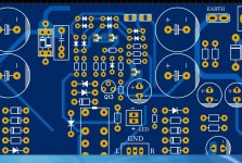
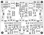
SMD resistors are 1206 / 3216 ?
1206 resistors and caps.
OK.
I'll try to make a THT version, let's see what comes out.
Ok, you could also omit dc detection part with smd but 1206 is not hard to solder...
I'll try to make a THT version, let's see what comes out.
I may do the same
.What was the "small modification" that gave less distortion? Just the bias current?
I may do the same
What was the "small modification" that gave less distortion? Just the bias current?
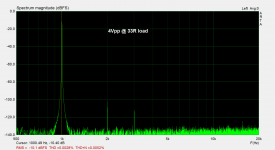
The smd 1206 parts on the pcb are for the dc detection circuit and could be omitted if you think it`s too hard for soldering... Raising the bias further improves the performance but only for low headphone loads like 32R, that of course requires higher heatsink profiles for higher dissipation. I`ll soon post final version of the schematic with measurements.

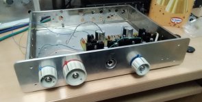
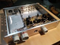
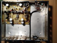
Because I had little time, I did a THT test.
All rights reserved.
Great, cheers!


Congratulations for this excellent amplifier that is really very performing!
I would like to know if you could consider making a version with separate grounds for each channel both as a power supply and as an output channel, to connect 4-wire headphones.
To make the circuit more flexible and allow the adoption of different types of power supplies and more easily keep the grounds separated starting to the transformer, this alternative version could provide two separate PCBs each including one channel amplification circuit and the DC detector.
To further improve performance, are there any semiconductors or other components that you recommend selecting?
Is it possible to know the open loop gain and open loop bandwidth?
What is the gain of the amplifier you made the measurements with?
Thanks again for your effort
Semola
Thanks, right now I have no time to do that, maybe in the future if you're not the only interested. I don't understand very well, only stereo amp with separate power supply connections?Congratulations for this excellent amplifier that is really very performing!
I would like to know if you could consider making a version with separate grounds for each channel both as a power supply and as an output channel, to connect 4-wire headphones.
To make the circuit more flexible and allow the adoption of different types of power supplies and more easily keep the grounds separated starting to the transformer, this alternative version could provide two separate PCBs each including one channel amplification circuit and the DC detector.
To further improve performance, are there any semiconductors or other components that you recommend selecting?
Is it possible to know the open loop gain and open loop bandwidth?
What is the gain of the amplifier you made the measurements with?
Thanks again for your effort
Semola
For the parts selection, you have everything in post #49.
Last edited:
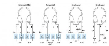
It refers to a balanced headphone amplifier.
Well, It could be done, but I don't see what's the advantage of this concept for headphone drivers? Any hints?
Btw, are you done with your build?
Is it possible to know the open loop gain and open loop bandwidth?
What is the gain of the amplifier you made the measurements with?
Thanks again for your effort
Semola
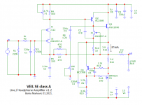
I'm not near the computer, to see the open loop, but if I remember correctly, ol gain is about 35-40dB, flat to almost 20KHz.
The measurements are done with configuration as on schematic, 3x, or ~9dB.
- Status
- This old topic is closed. If you want to reopen this topic, contact a moderator using the "Report Post" button.
- Home
- Amplifiers
- Headphone Systems
- VEIL SE Line / Headphone CFB amplifier