As promised, here is a new thread that evolved out of the old "Discrete Headphone Amp" thread. This design is as close as I have come to a knock-off of one of Nelson Pass's old designs, appropriating his "Aleph" driven current source lock, stock, and barrel. The schematic here shows the parts that I'm currently using (more or less), as well as a simulated THD plot. I took pains in this design to make sure that the input differential stage was as closely balanced as possible with no signal input, and this paid off in improved distortion, as well as reduced output DC offset.
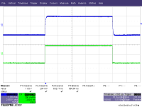
Gain-Phase plots are respectable, and will be shown in another post. I'll also show a square wave response when I get around to measuring it. However, from what I can see in the gain-phase plot, small signal square wave rise and fall times should be ~700ns.
Gain-Phase plots are respectable, and will be shown in another post. I'll also show a square wave response when I get around to measuring it. However, from what I can see in the gain-phase plot, small signal square wave rise and fall times should be ~700ns.
Attachments
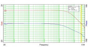
Here is an actual (not simulated) gain-phase plot of the current circuit after tweaking the compensation to the values shown in the previous post. 0 dB crossover frequency is 2.96 MHz, with a phase margin of 80.5 degrees. This is as far as I would want to push the current design, as the partial poles are starting to pile up after 3 MHz.
Attachments
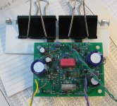

Here's a picture of one channel of the little beast...
I love your clips

Very nice work Wrenchone. One thing on the Aleph current source is to set the Aleph sensor resistor R13 and the M5 source resistor R8 in a ratio of R13:R8 of 1:2 in order to balance the reactive swing that the Aleph provides. This is explained in detail in the article on the Aleph by Mr Pass. You can check this by measuring the AC voltage across each resistor with say 100Hz excitation or even 1kHz if your DVM can handle it. Oscope is even better. The currents should be equal through both resistors.
I did the diddling and balancing in the simulation phase, where current probes are free... However, I fairly drastically altered the bottom output stage balancing the input diff pair, so I guess it's appropriate to check the Aleph drive balance again. I'll try first in sim ('cause it's easy), but also look at it in the real world with a current probe.
I'll show the PSpice Aleph optimizaion sims when I get back to work tomorrow. I'm also considering an option of this amp that uses Darlingtons rather than mosfets at the output if the sims show promise - it might, and the Darlington option would be way easier to build.
Wrenchone,
IMHO a Borbely EB602 with a modulated current source is a much cleaner concept than the Aleph dynamic current source.
https://www.diyaudio.com/forums/hea...borberly-eb602-200-revisited.html#post5492307
And that despite a 100W Aleph-JX being my first serious DIY project.
It avoids a FB loop (for the CS) within another FB loop (for the amp output).
Cheers,
Patrick
I'll look at that scheme of yours, but will continue with what I have so far. I have yet another modulated current source scheme waiting in the wings.
Dunno - I haven't put an ear to it yet. If there is, I may try using a capacitor multiplier on the main supply to provide a slow-rise feature.
I have cap Mx on all my HP amps now for the slow rise feature. No thumps at all. Plus quieter rails as bonus.
The Aleph CS senses the sum of the driving and modulated current of both halves.
This can lead to stability issues, requiring bandwidth limiting.
The one shown in the link senses the driving current only and use that to modulated the CS.
The result of that modulation is not sensed except in the global FB loop.
We found it to make quite a bit of difference in frequency response.
Cheers,
Patrick
Patrick, I heard you the first time. I will see how my ideas play out before trying yours - it's my learning experience, after all.
I got the Darlington-based Aleph amps stuffed yesterday. I deliberately omitted the current source stabilization capacitor C5 to see what happens. The simulation oscillated violently without it, and substituting a capacitor of 470p vs. 1 nF resulted in an inferior distortion simulation. We'll see what happens when I apply power.
The fet based version of this amp needed no cap in that position, either in simulation or reality. This is possibly due to the lower transconductance of the IRF610 fet at the lower bias levels of this headphone amp, as opposed to the much higher transconductance of the Darlington, or the large, heavily biased mosfet used in a lot of Aleph amps.
The fet based version of this amp needed no cap in that position, either in simulation or reality. This is possibly due to the lower transconductance of the IRF610 fet at the lower bias levels of this headphone amp, as opposed to the much higher transconductance of the Darlington, or the large, heavily biased mosfet used in a lot of Aleph amps.
- Home
- Amplifiers
- Headphone Systems
- Aleph-Based Headphone Amp