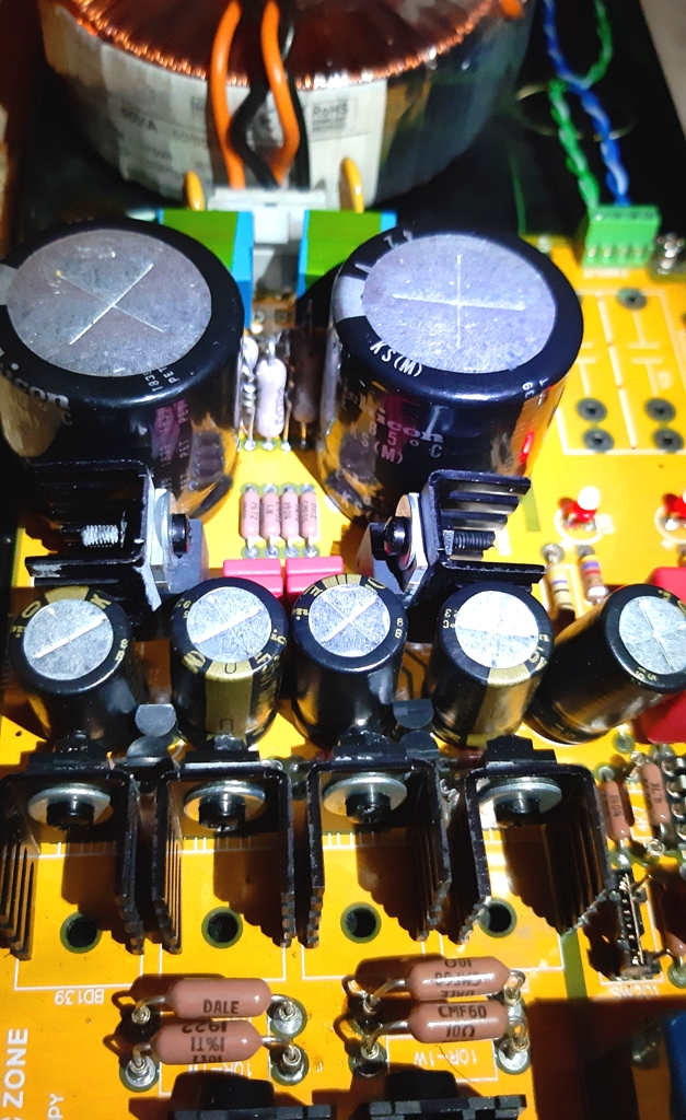
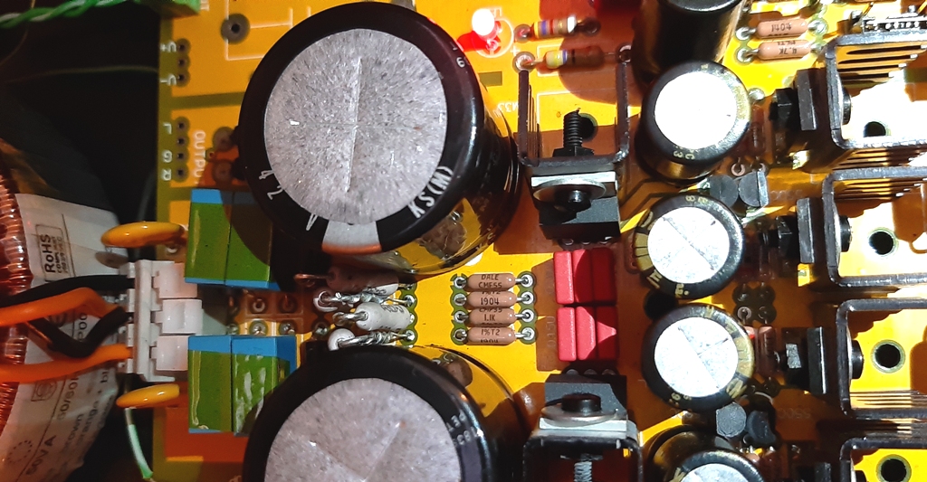
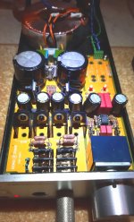
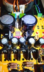
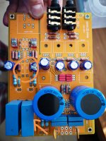
And here are a few picture of my 'upgraded' PCB, populated entirely by parts from Mouser (apart from the transformer).


Attachments
Nice. I used mouser parts too.
You have a long thread in HF about this amp and his mod. Find 'Lovely Cube". It's a very recommend thread.
I used 13v @1w zener. Used two in parallel is necessary for security.
You have a long thread in HF about this amp and his mod. Find 'Lovely Cube". It's a very recommend thread.
I used 13v @1w zener. Used two in parallel is necessary for security.
I have been reading this thread you suggested and it's quite interesting.
Thanks.
Eventually, I decided to go with the double trimpots method.
I also got a couple of XICON styroflex for trying in the 100pF caps position.
Could not find any BC560 on Mouser. They are obsolete..
However, I found a few old BC559/549 silver back transistors made by Philips in my stash.
Hopefully they are suitable for the job.
But how is the proper matching procedure for a lower DC offset?
Should I need to match hFE on each pair of 559/549, or to match the two 559s and the two 549s?
I'm waiting for the parts to arrive.
I'll post after I do the work.
Reconsidering BCL
Hiya,
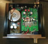
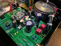
I've built my version recently because found my PCB bought long time ago.
I used CCS instead of 1.5k ohms in the diamond buffers created "Walt Jung buffers", and changed to global feedback with 150p local feedback cap around the OPA and ferrit beads on the output, outside the global FB loop.
LC filters are applied on supply rails.
Zener mod (remove 1.1k!) and biasing OPA into class-A are also have to be mentioned.
To avoid transformer buzz, DC-Blocker and 12V drop is applied in the primer circuit.
Sound: a completely new category than the original: open and virtually distortion free to human hearing (not just for measurement gears). 😎 To achieve this, sort the input caps or use NP0, and a good OPA!
Hiya,
I've built my version recently because found my PCB bought long time ago.
I used CCS instead of 1.5k ohms in the diamond buffers created "Walt Jung buffers", and changed to global feedback with 150p local feedback cap around the OPA and ferrit beads on the output, outside the global FB loop.
LC filters are applied on supply rails.
Zener mod (remove 1.1k!) and biasing OPA into class-A are also have to be mentioned.
To avoid transformer buzz, DC-Blocker and 12V drop is applied in the primer circuit.
Sound: a completely new category than the original: open and virtually distortion free to human hearing (not just for measurement gears). 😎 To achieve this, sort the input caps or use NP0, and a good OPA!
Attachments
Last edited:
help me please
Hi, I've searching for a while in the forum as I've the orange pcb. To find the parts is a horrible time consuming experience. Do you have a list or something will all the parts you bought? Its my first electronic build and its being harder than i thought as there are million of resistors in mouser to choose from.
I gathered all the pics, pdfs and part lists i found here in this tread so if you used them i already have them. Thanks and congratulations for such an awesome proyects
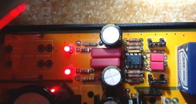
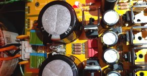
And here are a few picture of my 'upgraded' PCB, populated entirely by parts from Mouser (apart from the transformer).
Hi, I've searching for a while in the forum as I've the orange pcb. To find the parts is a horrible time consuming experience. Do you have a list or something will all the parts you bought? Its my first electronic build and its being harder than i thought as there are million of resistors in mouser to choose from.
I gathered all the pics, pdfs and part lists i found here in this tread so if you used them i already have them. Thanks and congratulations for such an awesome proyects
Hiya,
To avoid transformer buzz, DC-Blocker and 12V drop is applied in the primer circuit.
To avoid transformer buzz... If trafo has a hum - his place in garbage. 🙂
My BCL clone is now performing preamp duties, and very well I might add.
Since I have a little bit of headroom on the heatsinks for the output devices, I may raise bias for those at some point.
Since I have a little bit of headroom on the heatsinks for the output devices, I may raise bias for those at some point.
I have just ordered parts for mouser to complete my yellow board.
I cant find the transistors:
BC550CTA
BC560CTA
Ive got some in ebay but they are Chinese. I cant find originals ON semicondutor o fairchild
Can i get an alternative? Will to use Chinese parts be an issue?
Thanks
I cant find the transistors:
BC550CTA
BC560CTA
Ive got some in ebay but they are Chinese. I cant find originals ON semicondutor o fairchild
Can i get an alternative? Will to use Chinese parts be an issue?
Thanks
I can't see clearly at your photo how much space you have left, but it seems you need to replace those larger capacitors to make some space. I used MKT1813 0.33uF axial capacitors by Vishay there.
But i completely removed those input caps since I feed signal from AC coupled devices.
I now have just a wire link there.
For the two 0.022uF caps in front of the opamp, you can install 2 x 0.01uF polysterene capacitor (Xicon 23PS310) in each side.
One on top of each other.
Their width is 10mm, so typically they would fit in between the capacitors, albeit a bit tightly.
Measure the space among the capacitors to make sure they are 20mm or wider.
Last edited:
Just measure the hole spacing and use Mouser or Digikey to search for adequate Polypropylene Film capacitors. Since the width is restricted I suspect your choices might be quite limited, but you should be able to find something.
I've ordered a copy pcb for this amp and I already have a stabilised transformer, 120va which will fit in my case, but it's secondary voltage of 18-0-18. Everybody else is using 15-0-15, is an extra few volts going to be a problem for the regulators ? Spec suggests not, but thought I'd ask in case anybody has experience of this.
Also my genuine (modded by previous owner) BCL has blue LEDs in it, I'd have thought red more appropriate given blue is noisier, is this an early Lehmann build and did they change to red or yellow ?
I plan to use a Saligny rectifier in it, has anybody used one yet ? The lack of noise is the attractive feature.
Voltage is regulated by LM317/LM337, if you're using 18V transformers then that's an extra 4V to be dropped. You might need larger heatsinks for your regulators.
In this application I doubt LED colours will affect noise floor. The original Lehmann BCL measures 0.0025% thd max with the original blue LEDs.
Do you have a link to a source that suggests LED colour affect noise? As far as I know Lehmann only uses blue LED for the BCL and didn't change to different colours later on.

Hi, on the Whammy build thread Wayne suggests not using blue LEDs because they are noisier, red/amber are better choice. I'd not heard this before but I've never measured the noise an LED generates, not occurred to me that they might even be different.
I was just trying to think of a use for the 120VA 18V transformer I've got, it fits in a Musical Fidelity A1 but I was hoping to delay fixing that for a bit longer.... !
I was just trying to think of a use for the 120VA 18V transformer I've got, it fits in a Musical Fidelity A1 but I was hoping to delay fixing that for a bit longer.... !
- Home
- Amplifiers
- Headphone Systems
- [Headamp] upgrading a Lehmann BCL clone