Member
Joined 2009
Paid Member
Grasshopper - headphone amp for Grado
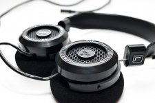
Headphone amplifier for Grado.
I just took delivery of some headphones. They have a low impedance of 32R which doesn't vary too wildly with frequency. It seems that they don't use a lot of voltage, line-level is enough. They will sit in their box until I have made something with my own hands to drive them.
I've never heard, designed or made a headphone amplifier before; time for Grasshopper to learn....
Attachments
Last edited:
Member
Joined 2009
Paid Member
I'm going to need a box and a power supply.
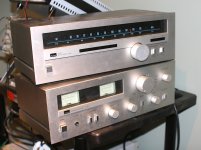
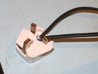
Pulled out two old Sansui boxes from the e-waste. A bit grubby, some scratches and dents. They're also originally from the UK and both wired into one mains plug for use with a voltage conversion transformer (for use here in Canada). I did find out who put it in the waste
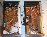
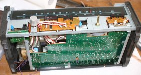
Taking off the lids I can see the Tuner is a nice old all-analogue design (T-60). It's low-end for Sansui but I see potential and will plan to use this as a source for the headphone amplifier. The Sansui power-amp (A-40) isn't so nice, undersized heatsink, standard 1970's topology and a lot of other bits in the signal path. The headphone amplifier will go into the tuner box, seems to me there's space for it alongside the guts of the tuner.
Because the tuner is equipped only to run on 240V I'll not be able to use it as-is, so I'll transplant the power transformer from the Power amp into the Tuner, which when used on my 120V mains will give me a useable voltage for the tuner. I see a few other bits I can transplant across including a headphone socket, a push-button switch and a volume control that will be needed for the headphone amplifier and what's left of the power amp will go back in the e-waste.
Pulled out two old Sansui boxes from the e-waste. A bit grubby, some scratches and dents. They're also originally from the UK and both wired into one mains plug for use with a voltage conversion transformer (for use here in Canada). I did find out who put it in the waste
Taking off the lids I can see the Tuner is a nice old all-analogue design (T-60). It's low-end for Sansui but I see potential and will plan to use this as a source for the headphone amplifier. The Sansui power-amp (A-40) isn't so nice, undersized heatsink, standard 1970's topology and a lot of other bits in the signal path. The headphone amplifier will go into the tuner box, seems to me there's space for it alongside the guts of the tuner.
Because the tuner is equipped only to run on 240V I'll not be able to use it as-is, so I'll transplant the power transformer from the Power amp into the Tuner, which when used on my 120V mains will give me a useable voltage for the tuner. I see a few other bits I can transplant across including a headphone socket, a push-button switch and a volume control that will be needed for the headphone amplifier and what's left of the power amp will go back in the e-waste.
Attachments
Last edited:
Hi,
First thing to ascertain is if they they sound better with low impedance
drive, e.g. a typical MP3 type player or phone, or sound better with
the old standard, that requires a 120R source resistance (typical
headphone out on an integrated amplifier).
Things are moving towards the former, due to 120R is totally
impractical for low V portable devices, but you never know.
rgds, sreten.
Member
Joined 2009
Paid Member
Good question - I don't know - so I looked at the Grado website and they do sell a headphone amplifier. But I can't see any published specifications for it. I then found a website where somebody tore one apart and it looks to be an Op-amp based unit with a topology that suggests it has enough feedback to ensure low output impedance. Seems that is the recommendation of Grado.
The Sansui amp had 220R resistors in series with the headphone output straight off the speaker outputs - I'm guessing these series resistors were originally designed for that purpose and have no place on a purpose built headphone amplifier.
So I'll go with your hint of where things are moving and look for low Zout.
Edit: the power supply in the tuner is single rail
Hi,
If its single rail look at :
Death of Zen Class-A - Use it as a headphone amplifier
You may be able to reuse the amplifiers heatsink.
I read up on the SR60e's and they are apparently not suitable for portable stuff.
So most likely they are best suited / optimised for higher impedance drive.
rgds, sreten.
Last edited:
Member
Joined 2009
Paid Member
Death of Zen Class-A - Use it as a headphone amplifier
I like the idea of a Class A amplifier, DOZ looks simple enough, close to the JLH I made recently. I'll look at some simple topologies for this project.
But these headphones need only 1 mW to reach nearly 100dB. Not sure a heatsink is going to be needed at all, or at least only something small.
Lots of interesting semiconductors pulled from the old A-40 amp that could be re-used here.
A bit more investigation reveals some more constraints, the power rail is around 12V only and the volume pot to be reused from the A-40 is 150k so I'll need a high input impedance.
I read up on the SR60e's and they are apparently not suitable for portable stuff.
So most likely they are best suited / optimised for higher impedance drive.
Perhaps some folk are saying this only because they are open-backed headphones not because they need higher impedance ?
Attachments

Last edited:
Good question - I don't know - so I looked at the Grado website and they do sell a headphone amplifier.
If you mean the RA1 it is a standing joke that you can replicate for a few dollars. A single NJM4556 opamp AC coupled.
Plenty of people find such an arrangement perfectly adequate though, and I don't intend that in any condescending tone, I've built lots of different opamp-based headphone amps and all are listenable with undemanding headphones. A pair of Shure e2c's have a very flat FR and impedance and are very efficient, so despite being 16 ohms you can still go louder than you need with many standard audio opamps without hearing much in the way of significant difference.
DC coupled with a servo, on-off pop protection, DC offset, battery failure protection, these are things to look for in a more sophisticated design, then the ability to swing more voltage or source more current to drive more demanding phones, although this introduces the danger of destroying phones or hearing with an inadvertent twist of the volume knob, so some preset gains might be desirable. Nested feedback composite opamp topologies can drive down distortion to very low levels.
Even AC coupled, DC offset in sensitive headphones can easily amount to tens or hundreds of LSBs due to leakage current.
Need higher impedance drive = need series resistors.
Last edited:
Member
Joined 2009
Paid Member
I read through the DOZ as a headlamp article - very good article. Seems that it is still over-kill for the power I need. But it linked another article for a lower power circuit (project 37). It's single ended class A based on the DOZ but with the upper output device configured as a current source.
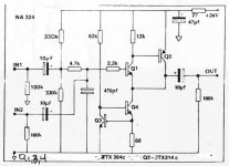
A bit more searching on the net turned up another very similar design which was attributed to NAIM (attached). Looks like I could get high input impedance, low output impedance and low parts count for ease of build. Is it too simple ?
Edit: thanks Counter Culture, just saw your post. I'm not sure how much sophistication I should aim for first time around, perhaps a simple discrete circuit will get me started before I try something with servo's etc.? I've built a few power amps with discreet parts but I've never made anything with an op-amp yet and don't have any in my parts bin either.
Attachments
Last edited:
I don't always see eye-to-eye with Dick Marsh, but most everybody admires his headphone amp, reckoned to be a very astute matching of components I think...
http://www.diyaudio.com/forums/headphone-systems/211394-marsh-headphone-amp-linear-audio.html
http://www.diyaudio.com/forums/headphone-systems/211394-marsh-headphone-amp-linear-audio.html
Member
Joined 2009
Paid Member
..Dick Marsh, but most everybody admires his headphone amp
Sounds interesting, is there a published schematic (I'm not buying the magazine if it's copyright because I can't openly discuss the circuit here) ?
Last edited:
Member
Joined 2009
Paid Member
Indeed a good read.
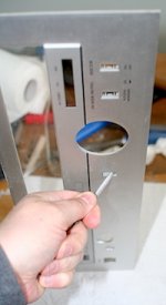
Some more progress on the box. I've pulled it apart to start drilling holes in for the new power transformer, transplanting of a small pcb with power supply fuse on board and making holes in the front panel for the headphone socket, volume control and selector switch.
Some more progress on the box. I've pulled it apart to start drilling holes in for the new power transformer, transplanting of a small pcb with power supply fuse on board and making holes in the front panel for the headphone socket, volume control and selector switch.
Attachments
Member
Joined 2009
Paid Member
Design criteria - getting the goals right ?
I'm going to use this headphone amplifier to listen to the radio in my office, that's why it's inside an FM tuner chasis
I'm going to use this headphone amplifier to listen to the radio in my office, that's why it's inside an FM tuner chasis
- Power Output: Assume average listening at 80dB at most with 30dB of headroom = peaks at 80 + 30 = 110dB. My Grado's are 1mW for 100dB so for 110dB I'll need 3mW peak. Into 32R headphones means 0.438V pk and 13.36mA pk.
- Gain: data sheet for the tuner says FM output is 0.7V and AM 0.25V so unity gain buffer is fine
- Output impedance: a damping factor of >20 needs Zout of 3R (no old fashioned output series resistors).
- Input Impedance: With a 150k volume pot I want an input impedance that is at least comparable and an input capacitance that is low enough to avoid h.f. roll-off . A low-pass RC filter with R=150k will have a 3dB point at 20kHz if C is less than roughly 50pF. For FM radio I don't think I can expect music signals above 15kHz.
- Noise Floor: FM stereo dynamic range tops out at 70dB. Allowing for 110dB peaks is a noise floor of 30dB which is 43.8uV at the 'phones.
- PSRR: 20mV of (Simulation) 120Hz ripple under-load and allowing only 43.8uV at the 'phones I need at least 20 Log (20,000/43.8) = 53dB PSRR.
- DC offset: I believe 1mV is fine, or 30uA. So I can use a cap-coupled output using good quality electrolytics (typ. 3uA at rated voltage).
Member
Joined 2009
Paid Member
Member
Joined 2009
Paid Member
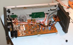
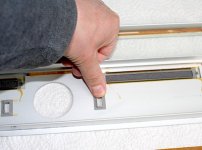
The extra switch, volume control and socket for the 'phones are now in place. Power transformer is hooked up.
Old rectifier diodes replaced by soft-recovery types, power supply electrolytic caps replaced with new (KME and Nichicon). A safety earth and new power cord fitted. Output caps and various power rail decoupling caps replaced with new. Mains switch and mains fuse installed on primary side of transformer (original tuner was switched on the secondary).
Front panel finished up but not installed yet.
It's coming along.
Attachments
Last edited:
Assuming you can get input impedance high / linear enough and dissipation is under control and power draw not an issue, that should work. 0.7 Vrms into 32 ohms means at least 30 mA of standing current, the more the merrier, so that may be pushing things a bit for TO-92 with a typical 13 V supply. I'd definitely be looking at what kind of heatsinking the regulator pass transistor has right now (and what sort of current the reg can supply anyway), and beef that up if needed.What about this approach, not necessarily novel but appears to meet all the needs. A CFP emitter follower suspended from a current source. PSRR is excellent, linearity is good, output impedance is <3R.
Also keep in mind you'll need a clean ~+Vs/2 (-ish) reference. R/RC divider with series R should do the job.
For a minimum of fuss, a unity gain follower with an NJM4556AD (or two combined via 2.2-ish ohms) isn't too bad really. ~9 mA idle for both channels.
Last edited:
Member
Joined 2009
Paid Member
I'd definitely be looking at what kind of heatsinking the regulator pass transistor has right now
Good point! I checked - the original unit was expected to produce 25V dc after the rectifier, then get dropped to 20V by an RC filter and then to 12V across the regulator pass transistor. The pass transistor would see an 8V drop across it and is a TO-220 bolted to a decent vertical pcb-mounted heatsink. It seems it was designed to be happy at 0.8W because I measured a current draw of around 100mA. With my modified power supply the pass transistor experiences a smaller voltage drop of 5.4V so for the same power dissipation I can draw 185mA, or 42mA per channel for the headphone amplifier.
Also keep in mind you'll need a clean ~+Vs/2 (-ish) reference. R/RC divider with series R should do the job.
I will bias the input transistor as you say with a divider but no filter C is needed because this is a unity-gain follower so I can run the divider off the amplifier output to ensure the bias is free of power rail noise. In this way there is also some bootstrapping so I don't have to use excessively high valued resistors for the bias chain in order to maintain a suitable input impedance.
The Sansui power-amp (A-40) isn't so nice, undersized heatsink, standard 1970's topology and a lot of other bits in the signal path.
Looks like the exact same heatsink that I pulled from a dead G-30. I recycled into my Pete Millett DCPP amp.🙂
jeff
I still don't entirely see how this would work (reliably). The circuit is essentially a fancified emitter follower whose DC voltage levels need to be defined somehow. I suppose you could use input transistor base current to generate the needed offset, but that's not exactly the definition of thermal stability.I will bias the input transistor as you say with a divider but no filter C is needed because this is a unity-gain follower so I can run the divider off the amplifier output to ensure the bias is free of power rail noise.
Member
Joined 2009
Paid Member
I still don't entirely see how this would work
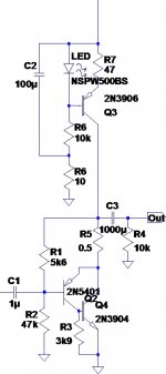
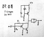
I hope the attached drawing will help explain my idea. There is a resistor potential divider made from R1 and R2. The current flow through R2 is 4 or 5 times larger than the base current into the input transistor so current gain temperature dependence should be limited. And with cap-coupled output there isn't a problem if the dc-level shifts around by a volt or so over normal operating temperatures. I ran a spice simulation using the TEMP command and the idle current through the totem pole has a slight negative temperature dependency (safe) - if the device models are correct of course.
The voltage at the base of the input transistor is set by the voltage drop across R2, i.e. V(base) = i x R2
The current through R2 is set by R1. The voltage drop across R1 is the Vbe of the input transistor which is around 650mV for a silicon bipolar transistor. If I choose R1 then the current is i = 650/R1 mA.
Say R1 = 5k6, then i = 0.116mA
And so a value of R2 of 47k would give V(base) = 0.116 x 47 = 5.45V
And so the voltage at the amplifier output is = 5.45V + 650mV = 6.1V which is roughly half way between the power rail and ground.
What do you think ?
Attachments
Last edited:
- Status
- Not open for further replies.
- Home
- Amplifiers
- Headphone Systems
- Grasshopper