Hi Mooly. Have you considered the added impedance of the output cap in your output impedance calculations. 1000uF adds another 4 ohms at 40hz reducing damping down to around 5-6 in the bass region.
Member
Joined 2009
Paid Member
I'm not Mooly, but I might choose to double up on the output capacitance 🙂Hi Mooly
Got the tuner hooked up to my TGM9 amplifier for a listen. It was too bright sounding. Then I realized that the FM de-emphasis was UK standard. I added some capacitance in the right place to change it for North America standard for FM de-emphasis. This brought it into balance - when compared with my Magnum Dynalab FM tuner.
This modified T-60 sounds pretty darn good !
Last edited:
Sorry about that Bigun. Been seeing alot of his posts the past couple days, must had his name stuck in my brain at the time of posting.
Member
Joined 2009
Paid Member
No problem, it would be great if Mooly was to drop in here too.
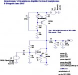
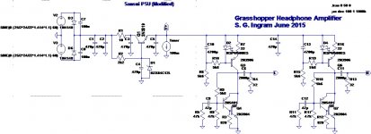
I ran the spice simulation for the circuit, of course it's 'just a simulation' but gives some grounds for optimism that the design approach is on-track.
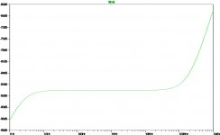
Output impedance (2nd attachment where the vertical axis reads 'V' but is is Ohms) is at 1R8, increasing to 3R2 at 10Hz, where damping factor will be at least 10.
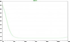
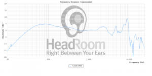
Frequency response (3rd attachment) looks better than my ears.
PSRR (4th attachment) exceeds the design criterion.
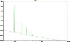
And FFT into 32R at 1mW (last attachment) looks tube-like nice. It is device model dependent and I may adopt a TO-126 packaged device for the build but I don't expect this to detract from a good result.
I ran the spice simulation for the circuit, of course it's 'just a simulation' but gives some grounds for optimism that the design approach is on-track.
Output impedance (2nd attachment where the vertical axis reads 'V' but is is Ohms) is at 1R8, increasing to 3R2 at 10Hz, where damping factor will be at least 10.
Frequency response (3rd attachment) looks better than my ears.
PSRR (4th attachment) exceeds the design criterion.
And FFT into 32R at 1mW (last attachment) looks tube-like nice. It is device model dependent and I may adopt a TO-126 packaged device for the build but I don't expect this to detract from a good result.
Attachments

Last edited:
Output at -9 dB? Isn't that a bit low? I mean, it should basically be a follower, and output impedance is quite low, hence not an awful lot of level lost there, so where'd the rest go?
Anyway, whatever the problem is, I can't reproduce it here. I hacked the schematic into LTspice myself, and gain comes out as about -1.44 dB with stock transistor models... and that's mostly to be blamed on input impedance. Distortion at 1 Vp in: -66 dB 2nd, -74 dB 3rd, -85 dB 4th (improving a few dB on a low-impedance source). Good enough for FM, I say.
Member
Joined 2009
Paid Member
Good question ! - well, you see low gain in my FFT because I used the 'volume control' (i.e. high source impedance) to dial down the output. So the signal was turned into heat - poof ! 🙂
I noticed that you used 1 Vpp which corresponds to more than 15mW (rms) at the headphones and I'm wondering if this is the right kind of signal level to be using for FFT analysis since I thought 15mW would be a 'how fast can I go deaf' plan ? - the Grado headphones will already be dangerous at 1mW and normal listening levels will be more like 100's uW where distortion will be negligible and mostly 2nd harmonic.
Interestingly and perhaps as expected, the distortion varies with the idle current. One might choose to 'dial in' the preferred sound through the use of an adjustable idle current. A higher idle current than I've selected could be used to drop the distortion further at high volumes. How low does the FFT need to go ?
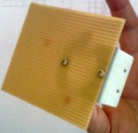
Attached: I've prepared a piece of Veroboard and a mounting bracket (taken from the Sansui amp) onto which the Grasshopper circuit will be assembled. I haven't used a proper piece of Veroboard for a loooooong time, so I'm looking forward to it !
I noticed that you used 1 Vpp which corresponds to more than 15mW (rms) at the headphones and I'm wondering if this is the right kind of signal level to be using for FFT analysis since I thought 15mW would be a 'how fast can I go deaf' plan ? - the Grado headphones will already be dangerous at 1mW and normal listening levels will be more like 100's uW where distortion will be negligible and mostly 2nd harmonic.
Interestingly and perhaps as expected, the distortion varies with the idle current. One might choose to 'dial in' the preferred sound through the use of an adjustable idle current. A higher idle current than I've selected could be used to drop the distortion further at high volumes. How low does the FFT need to go ?
Attached: I've prepared a piece of Veroboard and a mounting bracket (taken from the Sansui amp) onto which the Grasshopper circuit will be assembled. I haven't used a proper piece of Veroboard for a loooooong time, so I'm looking forward to it !
Attachments
Last edited:
True enough (my listening levels on 300 ohm HD580s tend to be in the 10s of mV), but it's always a good idea to look at maximum expected peak output, and that was about my ballpark figure for 32 ohm cans. Reaching 103 dB with a Grado SR60i would take about 0.4 Vrms (0.56 Vp), and that sim would have been for a more conservative 106-ish dB.I noticed that you used 1 Vpp which corresponds to more than 15mW (rms) at the headphones and I'm wondering if this is the right kind of signal level to be using for FFT analysis since I thought 15mW would be a 'how fast can I go deaf' plan ? - the Grado headphones will already be dangerous at 1mW and normal listening levels will be more like 100's uW where distortion will be negligible and mostly 2nd harmonic.
This is expected indeed. You can probably best see it with a plain CCS-loaded emitter follower. What happens is that transistor collector current is modulated by output current - a constant-current source being what it is, there is no other place for output current to come from. Now transconductance is inversely proportional to Ic, and its inverse dominates output impedance.Interestingly and perhaps as expected, the distortion varies with the idle current.
On positive peaks, collector current increases, and output impedance drops to a minimum. Hence that positive peak on the load will be a smidgen higher than it ought to be.
On negative peaks, collector current reaches a minimum, and output impedance reaches its maximum value. Hence the negative peak will get pulled down a bit by the load.
The result is that positive peaks become peakier, while negative peaks are flattened. Classic even-order distortion. Doing the math should reveal a dominant-2nd affair.
(Those who've paid attention may notice that adding some output resistance would be expected to reduce distortion. That's because we are looking at a voltage divider of 1/gm to the sum of Rout and Zload, so a given absolute variation of 1/gm as a result of given load current gives a smaller relative variation in load voltage. And in fact, add 32 ohms in series while doubling input amplitude, and distortion drops by about 6 dB.)
With a conservative well-behaved circuit like this, I might shoot for -60 dBr (2nd) / -70 dBr (3rd) @ 103 dB SPL out (0.56 Vp / 1.12 Vpp at the load in this case), 10 kHz. In your case that means 25 mA of idle current is the minimum. (The onset of clipping is just a few dBs higher up, so not too much dynamic range wasted.)One might choose to 'dial in' the preferred sound through the use of an adjustable idle current. A higher idle current than I've selected could be used to drop the distortion further at high volumes. How low does the FFT need to go ?
If you still want -80 dBr or better up there, however, it's more like 75 mA. 10 dB more idle current or 10 dB less signal, both cases amount to much the same here - dominant 2nd drops by 20 dB, 3rd by 30 dB, and so on. You can also calculate nth order intercept points and all that fun stuff from the RF world. Really predictable behavior as long as you stay a few dBs away from clipping. These are classic "you get what you pay for" circuits.
Member
Joined 2009
Paid Member
Wow - really good analysis of the situation, great learning opportunity !
My idle current choice will probably depend on heat dissipation. My plan is to fashion some metal fins and stick them on the transistors.
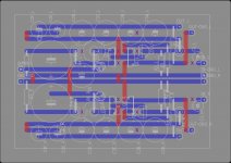
Attached - first attempt at a Veroboard layout 😛
My idle current choice will probably depend on heat dissipation. My plan is to fashion some metal fins and stick them on the transistors.
Attached - first attempt at a Veroboard layout 😛
Attachments


Last edited:
Member
Joined 2009
Paid Member
Member
Joined 2009
Paid Member
I have built up the Veroboard design. I ended up swapping the polarity of the input cap, it's not correct as drawn in the posts above. The values I used were:
LED - Fairchild bright yellow
R1, R4, R5 - 5k6
R2 - 47k
R3 - 820R
R6 - 18R (selected on-test to give current of 57mA per channel)
R7 - 8K2
C1 - 47u
C2 - 4,700u (takes a few seconds for CCS to start-up)
C3 - 4 x 470u plus 2 x 47u = total 1,974uF
C0 - 470u
Q1 - 2SA1142 (pnp)
Q2 - 2SC3423 (npn)
Q3 - 2N3906 (pnp)
Attachments
Member
Joined 2009
Paid Member
The power devices get warm but not hot enough to demand a heatsink. The bench supply shows 12V at 110mA total; voltage drop across R6 calculates to 57mA per channel - so good agreement there.
The dc bias at the input (base) of Q3 is 5.78V (left) 5.67V (right)
The dc bias at the output (emitter) of Q3 is 6.45V (left) 6.33V (right)
seems good there.
I added a 33R resistor load to the output of the left channel.
With no signal and shorted input I can just see some 'fuzz' on the oscilloscope with max gain (all knobs pulled out) which looks like +/- 100uV and represents all noise sources including my old O'scope so I'm not sure I have the means to measure the amplifier noise properly with my equipment.
Using the CRO probe calibration point, a 1kHz 0.5Vpp square wave - the output of the amp looks clean. The gain measures at 0.96.
With a sine wave (signal generator at around the same signal level):
2Hz - see some gain fall off, perhaps around 0.8
2Hz - 10Hz see phase shift, less than 60deg.
50Hz - clean, no phase shift and stable gain
1kHz - clean, no phase shift and stable gain
200kHz - clean, no phase shift and stable gain
looks ok so far
Attachments

Member
Joined 2009
Paid Member
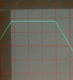
Clipping behaviour: limited on +ve swing by CCS. From scope with 1kHz sine wave I measured clipping around 1.8V +/-0.2V into 33R which is around 55mA and close enough to the CCS limit measured earlier. As expected, with a simple topology the clipping recovery is clean.
Attachments
Member
Joined 2009
Paid Member
Member
Joined 2009
Paid Member
I finally installed the veroboard amplifier inside the tuner and wired up the power. I wired up the output to the headphone socket using shielded twin-core. I wired up the input to the volume pot and then from the volume pot to the tuner output.
First impressions:
- it works !
- it's PLENTY loud enough with no gain, I had to keep the volume control at a low setting and I can see now that no Grado SR60 ever needs a headphone amplifier with gain, ever.
- with no antenna and in my basement it was plenty noisy but my sense is that I need to tame the treble for my ears (this I am convinced is the frequency response of the headphones rather than the amplifier; the tuner I've heard already and it's fine)
- not sure if I prefer the tuner in mono or stereo mode yet
Last edited:
Member
Joined 2009
Paid Member
Adding a switched Treble Cut
I have one extra switch on the front panel, one that I transplanted from the A-40 amplifier chassis onto the T-60. I installed it where the T-80 has a switch installed so there was already a spot on the pcb to solder the switch to. I'll use this to make a 'Treble Cut' so that I have some means to tame the treble when necessary.
This switch when used on the T-80 switches an R + C across the output as a 'noise reduction' circuit. I found a pair of Mylar 22nF caps on the old A-40 pcb and transplanted them into the spots reserved for the R + C filter. Then I connected the junction between the two caps to signal ground. This extra capacitance to ground is now switched in and out from the front panel whenever I need it.
The T-60 already incorporates an RC filter on each channel, 2k2 plus 3.9nF which has a corner frequency at 18.5kHz. Now I can switch in an additional 22nF to give an RC filter with 2k2 plus 25.9nF with a 2.8kHz corner frequency and a roughly -10dB cut at 9kHz.
Listening: the treble cut works just fine. It provides just the right level of trebly cut on 'forward' sounding music and can be switched out when not required. I also noticed that there was no turn-on or turn-off spike at the headphones but if you plug the headphones in then you get a nice 'bang'. Best not to hot-plug!
With volume turned all the way to maximum (tuned off-station) there's a faint background hum but at normal volume levels it becomes inaudible.
Attachments
Last edited:
Member
Joined 2009
Paid Member
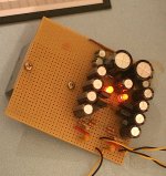
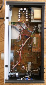
Top view of the finished unit with the lid-off.
At the top right is the power transformer (transplanted from the A-40).
At the top left is the new Grasshopper headphone amplifier built on overboard. The two red bobbins with square holes are the output inductors.
Centre on the right-side is the mains fuse pcb (transplanted from the A-40)
At the top right is the power transformer (transplanted from the A-40).
At the top left is the new Grasshopper headphone amplifier built on overboard. The two red bobbins with square holes are the output inductors.
Centre on the right-side is the mains fuse pcb (transplanted from the A-40)
Attachments
Member
Joined 2009
Paid Member
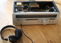
Here, attached, picture of the finished unit (lid off). On the left hand side of the front panel the new headphone socket and volume control (transplanted from the A-40) and the new Treble Cut switch just to the left of the large tuning knob.
Sounds very good
Sounds very good
Attachments
Member
Joined 2009
Paid Member
The box is closed and the unit is installed on my desktop at work. Reception is limited to strong stations due to short wire antenna (which will be upgraded) but I'm pleasantly surprised by the sound quality. Generally, I find that engaging the Treble Cut produces a more balanced sound with these headphones on 'popular music' channels.
Given the treble response of Grados (plus SR-80s being one of their brighter-sounding models if memory serves), I'm not surprised. Response with treble cut on probably is closer to some HD650s or similar "well-behaved" cans...
Interesting that you don't get any (audible) power-on/off transients. I may have to look at this in sim.
Interesting that you don't get any (audible) power-on/off transients. I may have to look at this in sim.
- Status
- Not open for further replies.
- Home
- Amplifiers
- Headphone Systems
- Grasshopper