@ammel It was 2k originally before I changed the BOM based on Stan's experience.
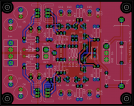
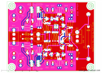
@everyone Attached is an image of the bottom metal layer of the Sapphire 4.0b board. As that middle-management type in Star Wars says "We've analyzed their attack, sir, and there is a danger" ...
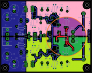
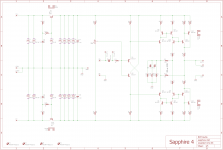
The red traces are the input to Q1,Q2 and the near-zero potentials on either side going into the trim pot. This is all high impedance area, biased to about zero volts by the voltage divider R4,5 between the power planes V+ and V-, colored green and purple.
You can see that these power planes go right up to the red traces. This presents a risk, as any accidental resistance from V+ or V- and those red traces will act in parallel with R4 or R5, pulling the bias voltage up or down. Since R4,5 are 100k, a few megaohms would be enough to move the bias value several hundreds of millivolts.
While it's unlikely to be a practical issue please be fastidious about not getting flux or grease or miscellaneous glop spread all over the area around the trim pot.
In future iterations I will address this by adding greater isolation or possibly a shield around the sensitive traces.
note: no I don't think this is what caused Stan's problems~
@everyone Attached is an image of the bottom metal layer of the Sapphire 4.0b board. As that middle-management type in Star Wars says "We've analyzed their attack, sir, and there is a danger" ...
The red traces are the input to Q1,Q2 and the near-zero potentials on either side going into the trim pot. This is all high impedance area, biased to about zero volts by the voltage divider R4,5 between the power planes V+ and V-, colored green and purple.
You can see that these power planes go right up to the red traces. This presents a risk, as any accidental resistance from V+ or V- and those red traces will act in parallel with R4 or R5, pulling the bias voltage up or down. Since R4,5 are 100k, a few megaohms would be enough to move the bias value several hundreds of millivolts.
While it's unlikely to be a practical issue please be fastidious about not getting flux or grease or miscellaneous glop spread all over the area around the trim pot.
In future iterations I will address this by adding greater isolation or possibly a shield around the sensitive traces.
note: no I don't think this is what caused Stan's problems~
Attachments
Last edited:
you wrote millivolts earlier though
"OL, says Fluke; the other side measures 271mv"
Sorry, my bad.
... power planes go right up to the red traces. This presents a risk, as any accidental resistance from V+ or V- and those red traces will act in parallel with R4 or R5, pulling the bias voltage up or down. Since R4,5 are 100k, a few megaohms would be enough to move the bias value several hundreds of millivolts.
While it's unlikely to be a practical issue please be fastidious about not getting flux or grease or miscellaneous glop spread all over the area around the trim pot.
note: no I don't think this is what caused Stan's problems~
I usually wash down a pcb with methyl hydrate or contact cleaner to take away all the excess flux and glop that can be there after working on a board. This allows me to see if there are any solder bridges or such. Sapphire 4 was no exception, I'm quite certain this was not an issue. But I see how easily it could be.
I like Sapphire 4
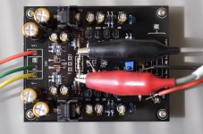
Today I listened to some favourite test tracks on Sapphire 4.0b, then put my Sapphire 3.0f boards back into the box as quickly as I could (sure am glad I used terminal blocks!) and listened again, then switched to 4 again as quickly as possible.
Conclusions: In 4, there is definitely more "air" in a more cohesive, natural soundstage than 3.0f. There is also a more dynamic sense of transients, such that the music has more snap to it, more vitality. The low frequency floor that I sense in 3.0f seems to have fallen away in 4: 4 is open and airy and natural, but with maybe a hint of warmth. 4 gives me the best sense yet of recording studio space.
If fact, I was kind of shocked that when listening through my 3.0f boards after hearing 4 just minutes previously, the music just kind of laid there, by comparison. In 4, my headphone listening has reached a new standard.
A new recording in my collection just a week or so ago is Bill Frisell's "When You Wish Upon A Star"; I love his cover of "You Only Live Twice", and I'm already well familiar with it - it's the kind of track you want to hear again, immediately. It showed the comparisons I mention most obviously. I could feel the recording space.
Another great recording that shows these contrasts is "Muddy Waters Folk Singer". This is another well-engineered recording that plays so well.
Woodsman's "All Tangled Up" is a dense sonic texture that recedes a bit into itself through 3.0f; Sapphire 4 restores the percussive snap that makes it work.
JJ Cale's "To Tulsa And Back" is a nice recording that also shows these contrasts: I've been focusing on "Chains of Love". I could go on...
No question in my mind: 4.0b has left Sapphire 3.0f behind.
My hat is off to you, Richard!
Note: my Sapphire 3.0f is running an SMC-mount AD8610 op amp on a Brown Dog adapter. I preferred the 8610 to the OPA134. I have not heard the later version of 3 that accommodates designer op amps, so take my comparison notes with that knowledge in hand.
I just put it out there because it came up as I was reviewing possible causes.
RJ,
And it is good of you to do so.
The following link is to an article written long long when when super-regs were state of the art. But the subplot is interesting: some things never change.
http://waltjung.org/PDFs/Improved_PN_Regs.pdf
bench notes:
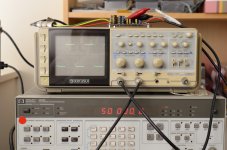
I tried the feedback modification where R3 is connected to the output rather than the current source node R11-R12. R2 was 100 ohms, R3 was 2k21. Test load 47 ohms, 60 mV input, 50 kHz square wave. Works as advertised with C2 = 0. The expected bandwidth is about 2 MHz.
*****
BOM 40b9 attached. R6 changed to Bourns type, and recommended values for R2 R3 with the mod have been changed as I realized the gain formula is different in this configuration. It's R3/R2+1, not 0.5 R3/R2+1 as it is with the normal connection.
Attachments

Last edited:
No question in my mind: 4.0b has left Sapphire 3.0f behind.
My hat is off to you, Richard!
Thanks Stan for taking the time to do a comparative review! Much obliged.
Last edited:
bench notes:
I tried the feedback modification where R3 is connected to the output rather than the current source node R11-R12. ...
Listening test? Have you tried this or are your 4.0b boards currently farmed out to another builder? You wrote that 4.0b, compared to your last 3 build, showed some recession of treble intensity and transient response. I didn't get that from my listening and that leaves me wondering what else I may have missed in skipping the last iterations of 3.
Back to my board inequity. I'm tempted to try another set of zeners. Except that it's working and sounds so lovely I'm reluctant to take it apart again. That's how I got stuck on AD8610's. My experiment with designer op amps many posts back was a crashing failure, so I didn't try any others.
The evidence suggests that I follow your lead, but something tells me I need to find the bug first.
I have the boards still, just not cased up. I checked the mod to make sure it passed square waves without flying off its rails, that's it so far.
With a resistive load it works as simulated, but the real world influence of the headphone inductance for example is not considered.
With a resistive load it works as simulated, but the real world influence of the headphone inductance for example is not considered.
Some thoughts about what features to bake in (and which to remove) on the next board revision.
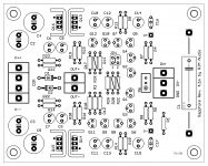
In addition to increasing the clearance between the power planes and the input, the main thing I feel needs to be addressed is gain selection.
This is done with a two position jumper and three resistors for R2, one fixed and two optional. Three gain options can be configured, 8-15-25 dB for example.
The other is the feedback connection. Rather than the flying resistor mod, what you have here is two R3 positions on the board. Use R3 for the usual connection, or populate R3X instead of R3 if you want to connect to the output.
I considered making this a jumper setting, but the thing is the values of R2 to use with R3X are different than for R3, so even if R3 was switchable you'd have to pull out all R2 and add new resistors to match. So realistically the board would have to be built as one or the other, which is why I opted to nix the second jumper.
Removed the V+ V- pads, and the T- pad (voltage TRIM an be referenced to case, COM, etc...)
Input welcome.
Attachments
Last edited:
Sapphire 4 Transformer Options
Has anyone has experience of the recommended Dual transformer vs a single transformer to power the 2 boards?
The reason for the question is that I have an existing chassis which would fit a single transformer easily, but will struggle with two.
I'm looking at the suggested alternative 'medical grade' Triad VPM24-1040 as a single transformer, is this sufficient in VA rating? There is a 50VA version available which would fit the chassis.
Any thoughts on sound quality of 1x vs 2x transformers greatly appreciated.
Andy
If it means anything to you I will probably do future builds with just one transformer. Two VPMs just gets ridiculous in terms of total bulk. They are so much bigger than the VPTs and I'd rather have one VPM, with it's shield and screen, than two VPTs lacking either.
Triad VPM24-1040 is 1.04A/25 VA while the VPM24-2080 is 2.08A/50 VA. Since the price isn't dramatically different I'd get the biggest which still fits conveniently in the case, but I wouldn't lose sleep over "only" using 25 VA, it's enough even for stereo.
Triad VPM24-1040 is 1.04A/25 VA while the VPM24-2080 is 2.08A/50 VA. Since the price isn't dramatically different I'd get the biggest which still fits conveniently in the case, but I wouldn't lose sleep over "only" using 25 VA, it's enough even for stereo.
Last edited:
Sapphire 4.1m
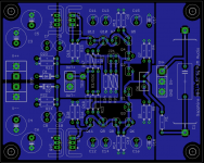
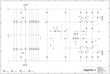
There were some layout tweaks in development, but the production boards 4.1m are not very different from 4.1d introduced above. Will have in hand by late April.
There were some layout tweaks in development, but the production boards 4.1m are not very different from 4.1d introduced above. Will have in hand by late April.
Attachments
No, the 70x90 indicates that the mounting holes conform to the metric standard for RJM Audio boards. The boards are 80x100, like before, and the mounting holes are the same also in this instance. The "70x90" label makes it explicit that this board conforms to the latest standard which I am working to make all my projects conform to, as:
1. 80x100 boards
2. 70x90 M3 mounting holes
3. 4 pad, edge mounted power input V++, COM, COM, V--
4. (5 pad edge mounted I/O IN+,IN-,GND,OUT-,OUT+) <- this could not be managed for the Sapphire layout unfortunately
VSPS200, CrystalFET, Phonoclone 3.8a, and Sapphire are compliant. VSPS300 and the old Phonoclone 3.5h are not.
Last edited:
No, the 70x90 indicates that the mounting holes conform to the metric standard for RJM Audio boards. The boards are 80x100, like before, and the mounting holes are the same also in this instance. The "70x90" label makes it explicit that this board conforms to the latest standard which I am working to make all my projects conform to, as:
1. 80x100 boards
2. 70x90 M3 mounting holes
3. 4 pad, edge mounted power input V++, COM, COM, V--
4. (5 pad edge mounted I/O IN+,IN-,GND,OUT-,OUT+) <- this could not be managed for the Sapphire layout unfortunately
VSPS200, CrystalFET, Phonoclone 3.8a, and Sapphire are compliant. VSPS300 and the old Phonoclone 3.5h are not.
Thank you for answer. Also for sharing your great work to public.
This project is very interesting and looks promising.
I thought it would be great if I can use hammond case. (1455T2201 or 2202)
With current PCB size, I need to put PCB one side on PCB rail, but the other side with stand-off. But it seems some resisters will short to chasis..
Maybe I will modify layout myself when proto phase is finished.
")
I will look forward to your result with Sapphire 4.1
Cheers,
- Home
- Amplifiers
- Headphone Systems
- RJM Audio Sapphire Desktop Headphone Amplifier