As of right now, the only items left are a few BAL-SE boards. I'll post these up for sale in a few weeks when absolutely everything is done shipping. There are no more kits, and all other boards have completely sold out.
Payments that have not been received on the list are not people who haven't paid, they are people who have amplifiers in their order and I haven't even requested payments since some parts were back ordered for the amps.
Everything will be finished by the end of next week, and I'll let everyone know what's still available after that.
Regards,
Owen
Well, the tread is like 120 pages long.
I can wait if none are available.
search this thread using the button in the top right for the phrase 'are there any PCBs left?', I have lost count the number of times the same question has been asked and answered, so it should not be hard to find.
@opc: btw sorry i keep forgetting about the bal-se pcbs. i thought that and then for some reason remembered that they had sold out too, but i was wrong...again
ROTFLMAO or simply lol?
lol, qusp, you have consisently been right about ALL the important aspects, and next to opc, the most important contributor. The two of you have made an awesome team and I will always value your curmudgeonliness (sp?).
The notion of qusp's portable wire seemed ludicrous until I listened to my Edirol thru the BAL-BAL. It is not as musical as quad BB1704's but . . .
The 'wire' is absolutely a homerun, opc.
. . . but i was wrong...again
lol, qusp, you have consisently been right about ALL the important aspects, and next to opc, the most important contributor. The two of you have made an awesome team and I will always value your curmudgeonliness (sp?).
The notion of qusp's portable wire seemed ludicrous until I listened to my Edirol thru the BAL-BAL. It is not as musical as quad BB1704's but . . .
The 'wire' is absolutely a homerun, opc.
My boards just arrived! Lol - I guess that I won the USPS postal-delivery lottery this time.
Now I just need to build these up and get some megawattz coming out! 😀
Now I just need to build these up and get some megawattz coming out! 😀
My boards just arrived! Lol - I guess that I won the USPS postal-delivery lottery this time.
duzThis bode well for the HigherWire frankenwire?
Just arrived
Whoop... a small parcel from Canada arrived roughly 20 minuets ago containing my se-se & psu kits 🙂
I was expecting it to be small but this is miniscule 😀 ... it's going to be lost within the case I've bought, but that'll give me more than enough room to add a DAC latter on [possibly Rocket Scientist's ODAC].
Not much free time at the moment, so it'll be just over a week before I get to build and case this little beauty.
Thanks to opc for all the time and effort put into this project, and to everyone else who's contributed here, I'm sure I'll be positively singing The Wire's praises once it's up and running 🙂
Last edited:
duzThis bode well for the HigherWire frankenwire?
Probably not for awhile. 🙂 I'm going to build up a standard Wire first, then a +/-18V O2 amp for 600R phones. I like that name! 🙂
Probably not for awhile.
Would you mind if some of us ran with your HigherWire idea?
Would you mind if some of us ran with your HigherWire idea?
Go right ahead! 🙂
Rework for LME49990->LME49860
Draft 0.9 simple pcb rework, poorly half implemented.
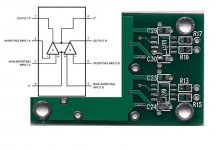
The attached image shows the pin-out for the 49860 and the underside of a rework SE-SE pcb. Note that the solder mask has been removed from the trace from C24 to U9 and that trace severed and routed to a different pad between C30 and U11. I believe that is the extent of the pcb surgery required. Before and after -- that simple.
To install the 49860, Pins 2 and 7 should be lifted and the others soldered to their matching pad. A blue wire from the pad under 7 to pin 5, and from pin 7 to the pad under pin 2 is all that is left. agdr rejoice (Wolfsin thinks).
Advice on how to silence opamp A appreciated as well as best routing of blue wires.
Draft 0.9 simple pcb rework, poorly half implemented.
The attached image shows the pin-out for the 49860 and the underside of a rework SE-SE pcb. Note that the solder mask has been removed from the trace from C24 to U9 and that trace severed and routed to a different pad between C30 and U11. I believe that is the extent of the pcb surgery required. Before and after -- that simple.
To install the 49860, Pins 2 and 7 should be lifted and the others soldered to their matching pad. A blue wire from the pad under 7 to pin 5, and from pin 7 to the pad under pin 2 is all that is left. agdr rejoice (Wolfsin thinks).
Advice on how to silence opamp A appreciated as well as best routing of blue wires.
Attachments
Soldering Advice
I received my SE-SE/PSU kit yesterday and am looking forward to starting on it (as soon as work allows). Thanks opc for making this available. This will only be the second SMD PCB I have ever assembled (the first, a 41 Hz T-AMP worked, so I am emboldened to try again!) and I am not particularity concerned about most of it EXCEPT for how to handle the tabs on U10 and U12 (the LME49600).
So can anyone give me some suggestions on how to best solder that tab? I have a quality temperature controlled iron and have been soldering things together for a long time. But I just don't want to damage the board or the parts so a little guidance would be much appreciated.
Thanks!
Terry
add some flux to the large pad, tack down one or 2 of the legs to hold it in place, change to a high mass chisel tip or similar, crank the iron right up about 2/3 of the dial and let the tip heat up well, heat the junction of pad and tab for maybe 3 seconds before starting to flow solder, flow along the tab, dont be afraid of overheating it unless you really linger too long, or have to reheat multiple times. the key is to use enough high heat and have enough thermal mass to get in there, get the job done and get out. you are much more likely to overheat it by not using enough heat and having to hang around too long.
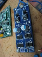
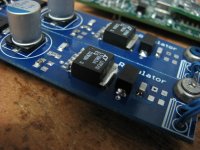
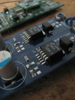
below is a few pics, its not the wire and its not the LME49600, but its an LT1963A linear reg in the same package (handy little reg board my mate Tom laid out, also takes LT1764A adjustable from 1.2-20v and up to 3A, although probably about 1A with this amount of copper), so illustrates the point fine and should show the amount of flow you need on the tab.
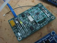
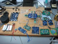
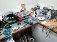
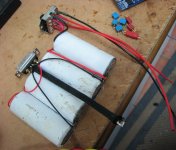
I've also included pics of the kickass (if a bit rotund) A123 battery i'm using for the portable as well as a pic of the buffalo 2 modified for slightly higher performance with lower impedance caps, but mainly modified for low profile and u.fl smd bnc for digital inputs. as well as a pic of the current, slightly out of control state of my workbench in the middle of a few projects. this could happen to you too kids. projects include test layouts for combining all 4 channels of ackodac as well as neatening up the wire routing while i'm at it (theres another 2 channels of the last non-ptfe ackodac there too in green) into a 2 case build with separate PSU and the new power supplies that go with that, the low noise gate bias supply for SEN and CEN IV as well as the IVs themselves, Titan USB testing for multichannel, the reg mentioned as well as the portable dac; plus various jobs for work
I really need an extractor fan, though the workspace is well ventilated
below is a few pics, its not the wire and its not the LME49600, but its an LT1963A linear reg in the same package (handy little reg board my mate Tom laid out, also takes LT1764A adjustable from 1.2-20v and up to 3A, although probably about 1A with this amount of copper), so illustrates the point fine and should show the amount of flow you need on the tab.
I've also included pics of the kickass (if a bit rotund) A123 battery i'm using for the portable as well as a pic of the buffalo 2 modified for slightly higher performance with lower impedance caps, but mainly modified for low profile and u.fl smd bnc for digital inputs. as well as a pic of the current, slightly out of control state of my workbench in the middle of a few projects. this could happen to you too kids. projects include test layouts for combining all 4 channels of ackodac as well as neatening up the wire routing while i'm at it (theres another 2 channels of the last non-ptfe ackodac there too in green) into a 2 case build with separate PSU and the new power supplies that go with that, the low noise gate bias supply for SEN and CEN IV as well as the IVs themselves, Titan USB testing for multichannel, the reg mentioned as well as the portable dac; plus various jobs for work
I really need an extractor fan, though the workspace is well ventilated
Attachments
-
 assorted dacs, regs and IVs ready for action_07Jan2012_0370.jpg155.4 KB · Views: 549
 -
 assorted dacs, regs and IVs ready for action_07Jan2012_0382.jpg124.3 KB · Views: 520
 -
 assorted dacs, regs and IVs ready for action_07Jan2012_0384.jpg93.9 KB · Views: 519
 -
 assorted dacs, regs and IVs ready for action_07Jan2012_0373.jpg165.2 KB · Views: 516
 -
 assorted dacs, regs and IVs ready for action_07Jan2012_0378.jpg173.5 KB · Views: 327
 -
 assorted dacs, regs and IVs ready for action_07Jan2012_0379.jpg148 KB · Views: 308
 -
 kickass battery.jpg119.2 KB · Views: 272
Last edited:
Thanks CafeNoir and qusp. Those instructions are very helpful. I've also been hoping to play with the LT1963A and 1764 but frankly have been holding off due to my concerns about soldering them. BTW, any possibility those layouts -or better yet the PCBs-could be made available? Could be very handy. (and my bench is probably in worse disarray than yours).
Thanks again to both of you.
Terry
Thanks again to both of you.
Terry
Nice mess, dOOd(s)!
Wolfsin feelzSlightly more relaxed now about allowing others to glimpse his lousy soldering 🙂 A messy desk is a sign of an orderly mind!
@ilardi -- pls post pix of yours so we can all feel better.
Wolfsin feelzSlightly more relaxed now about allowing others to glimpse his lousy soldering 🙂 A messy desk is a sign of an orderly mind!
@ilardi -- pls post pix of yours so we can all feel better.
copper foil resistance for planes
With copper foil having 0.000498 ohms/square
for 1-ounce/foot^2 foil, a substantial current
that chooses to use the headphone amp as a
path could degrade the signal quality.
1 amp from some stepper motor would induce
498 microVolts into any square of copper the
current flows thru, and such particles will use
all possible paths, proportional to conductance.
Two vias of diameter 0.06" (round), separated by
0.06" spacing will have ~ 1 square of foil resistance between
them. If those vias are the two ends of the 1amp
current, the vias would be 498 uV apart.
Thus Ground indeed is Just a Cruel Joke.
Um, pardon?
And your point is exactly? I must be missing something.
- Home
- Amplifiers
- Headphone Systems
- "The Wire" Ultra-High Performance Headphone Amplifier - PCB's