I just noticed one of the smoothing caps was bulging so I decided to replace all 8 with 2200uf 25v Rubycon YXA capacitors but after re-assembling it would not power on!
I think they are low ESR caps after doing some research so maybe that's why it won't power on? I was told that low ESR caps pre/post regulators is a bad idea.
I don't think that switching to Low ESR caps could be the cause of your problem. Are you sure that the wiring is correct and the caps are inserted in the correct order (not reversed?). Maybe you can post a picture?
By the way, I have found out that the resistors which are included in the kit version are not 'real' metal film resistors, but carbon composition resistors instead. They are pretty unstable (about 700 ppm/C!) with temperature and have a negative response (higer temperature gives lower resistance), which is common for carbon resistors (for metal film you expect the opposite). This should not really harm the amplifier, but it is of course not ideal since there is quite some temperature fluctuation in the first few minutes after power on. Also carbon composition resistors tend to hiss more. I have replaced them with better Vishay resistors. So be carefull when using the kit components or buying resistors from Ebay
") .
.My JLH, Vintage Transistor
using vintage transistor is much more fun and seemed elegant rather than too much complexity.
I don't have 100u inductor in hand, so I use 22 Ω resistor in the power supply.
Trafo is 17Vac 450mA.
regards
using vintage transistor is much more fun and seemed elegant rather than too much complexity.
I don't have 100u inductor in hand, so I use 22 Ω resistor in the power supply.
Trafo is 17Vac 450mA.
regards
Attachments
Hi, got a kit for the JHL dirt cheap on fleabay, I really don't even know if they are any good( the most common kit on there I think )?
At 14USD shipped, I figured it would be entertaining to solder together atleast.
Do any of you have any experience with this kit?
I will probably not use all parts in the kit, I'll probably go for better parts in some spots.
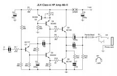
The same design as the one I won (JSDZ):
JHL kit
At 14USD shipped, I figured it would be entertaining to solder together atleast.
Do any of you have any experience with this kit?
I will probably not use all parts in the kit, I'll probably go for better parts in some spots.
The same design as the one I won (JSDZ):
JHL kit
Any updates over here?
Well guys, okay, okay, I have added some ventilation holes at last ;-). I do not not really like holes in the cabinet, but I found a way to 'camouflage' them more or less by making use of rubber gromets. I also added a different knob. So again a bit of improvement. I am still enjoying the amp. I mentioned that there are nice DC protection kits, dedicated for headamps on ebay using an UPC1237 IC. I am thinking of adding that as well, not because of necessity, but well... tweaking is fun.
Some pictures:
Well guys, okay, okay, I have added some ventilation holes at last ;-). I do not not really like holes in the cabinet, but I found a way to 'camouflage' them more or less by making use of rubber gromets. I also added a different knob. So again a bit of improvement. I am still enjoying the amp. I mentioned that there are nice DC protection kits, dedicated for headamps on ebay using an UPC1237 IC. I am thinking of adding that as well, not because of necessity, but well... tweaking is fun
.Some pictures:
An externally hosted image should be here but it was not working when we last tested it.
An externally hosted image should be here but it was not working when we last tested it.
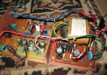
Started putting my kit together.
I'll use a DC-servo (using an OPA2134, if that is not suitable, I have many other opamps to chose from), I've added a wima 1uF to each of the 470nF input caps.
Swapped all 100uF caps to 180uF elna RJH's.
I will not populate the reg part of the board as I'll use off-board power supply and voltage regulation.
I have had limited luck in simulations(spice) with a LM3x7CS-TL431-shunt regulator using D4xH11's.
The neg side of the reg has a lot higher power dissipation compared to the pos side.
Could be the LM337 spice model I use.
I have also realized that I need to get another xformer for this build as the one I have and was planning to use probably is way under-sized @ 12-0-12VAC 1200mA.
Oh, almost forgot...I changed all 100nF, 330pF and 220pF for wima's.
About the reversed polarity caps, what would be best there?
I have 220uF/10V Silmic, 180uF/25V RJH, 470uF/25V rubycon ZL, 270uF/16V Sanyo SEPC, 220uF/10V Nichicon FG(only have two of those and they are not cheap) and possibly some 100-220uF/10V cerafine.
The only mods I am planning except the ones mentioned, is swapping the 3V3 zeners for 4(?) x 1N4148 in series.
About the DC-servo, I take signal from each channel at the emitter of the tip41? "Inject" the output of the servo between the input cap (in my case 1uF+0.47uF)and the 4K7 resistor?
I guess I should remove the trimpots and jumper there instead? Or leave the trimpots in?
Any ideas for external power supply and regulation is always welcome.
I currently use 32ohm headphones, Goldring DR-150's.
I will upgrade, but not in the near future.
The 32ohm HP's means I could lower bias and gain a bit without SQ suffering?
I will raise the output resistor from 2R2 to 68R as suggested.
Anything I have forgotten or missed?
Thanks for all info in this thread.
Hi,
Are these the correct connection points for a DC-servo?
Built one from the schematic in this thread, I figured I'd use one of my OPA2134's in it.
I used Rubycon 470uF ZL on the outputs, swapped the 2R2 for 68R and use Elna RJH 180uF for the 100uF spots.
470nF is paralelled with Wima 1uF on the bottom side.
0R that was already soldered in before I read about them are paralelled with tinned Cu wire on the bottom side of the PCB.
Still to do is amongst other things is to swap 3V3 Zener for 4x 1N4148 in series in the opposite direction of the Zener(correct?).
I will also put VRAM heatsinks with selfadhesive termal interface material directly on the TIP41C's to help with dissipation.
Are these the correct connection points for a DC-servo?
Built one from the schematic in this thread, I figured I'd use one of my OPA2134's in it.
An externally hosted image should be here but it was not working when we last tested it.
I used Rubycon 470uF ZL on the outputs, swapped the 2R2 for 68R and use Elna RJH 180uF for the 100uF spots.
470nF is paralelled with Wima 1uF on the bottom side.
0R that was already soldered in before I read about them are paralelled with tinned Cu wire on the bottom side of the PCB.
Still to do is amongst other things is to swap 3V3 Zener for 4x 1N4148 in series in the opposite direction of the Zener(correct?).
I will also put VRAM heatsinks with selfadhesive termal interface material directly on the TIP41C's to help with dissipation.
Hi Guys,
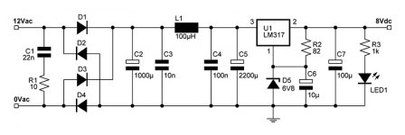
Today I have fulle completed the JHL headamp according to my initial plans. I've added a little circuit that protects the headphones from DC + a separate dedicated PSU. A nice feature of this PCB is that has a little delay circuit as well, so the servo has some time to settle, minimising DC before any signal is conducted to the headphones. It also inmidiately switches off the relay when the amp is switched off, so no switch noises are transmitted. Of course this board is modified as well, according to some of the suggestions posted here:
Headphone protector | Rock Grotto
I am pretty statisfied with the result
An externally hosted image should be here but it was not working when we last tested it.
An externally hosted image should be here but it was not working when we last tested it.
Nice looking buildHi Guys,
Today I have fulle completed the JHL headamp according to my initial plans. I've added a little circuit that protects the headphones from DC + a separate dedicated PSU. A nice feature of this PCB is that has a little delay circuit as well, so the servo has some time to settle, minimising DC before any signal is conducted to the headphones. It also inmidiately switches off the relay when the amp is switched off, so no switch noises are transmitted. Of course this board is modified as well, according to some of the suggestions posted here:
Headphone protector | Rock Grotto
I am pretty statisfied with the result
An externally hosted image should be here but it was not working when we last tested it.
An externally hosted image should be here but it was not working when we last tested it.
Hello, I assembled this amp but I have a buzz noise.
Amplifier is not in chassis it is PCB and transformer only for now.
I connected earth pin from the outlet to amplifier input ground pin - noise disapeared, but when I connected sound source i got a lot of high frequency noise, so i disconnected earth from outlet and input ground pin.
So how should I connect amplifier and outlet earth pin?
Worked a bit more on this headamp today.
GPU grade TIM, non-conductive
VRAM heatsinks on the TIP41C's
Swapped the 3V3 zeners for 4x 1N4148 in series
Mock-up with the DC-Servo
That's about as far as I got today
An externally hosted image should be here but it was not working when we last tested it.
GPU grade TIM, non-conductive
An externally hosted image should be here but it was not working when we last tested it.
VRAM heatsinks on the TIP41C's
An externally hosted image should be here but it was not working when we last tested it.
Swapped the 3V3 zeners for 4x 1N4148 in series
An externally hosted image should be here but it was not working when we last tested it.
Mock-up with the DC-Servo
An externally hosted image should be here but it was not working when we last tested it.
That's about as far as I got today
Got this yesterday(I think, or the day before).
I have one in my B1 preamp(50K), and I think they are very nice.
"Dact" style stepped attentuator
Really only missing the R-Core 30VA 2x15VAC that is on it's way..and I need to build a decent power supply, then the headamp ready for testing.
Apart from swapping 2R2 on the outputs for 68R and fixing cap polarity, putting in better caps, DC-servo, 3V3 zener swapped for 4x 1N4148 in series...what else is there to do that will improve stability and SQ?
HP's are 32ohm.
I have one in my B1 preamp(50K), and I think they are very nice.
"Dact" style stepped attentuator
An externally hosted image should be here but it was not working when we last tested it.
An externally hosted image should be here but it was not working when we last tested it.
Really only missing the R-Core 30VA 2x15VAC that is on it's way..and I need to build a decent power supply, then the headamp ready for testing.
Apart from swapping 2R2 on the outputs for 68R and fixing cap polarity, putting in better caps, DC-servo, 3V3 zener swapped for 4x 1N4148 in series...what else is there to do that will improve stability and SQ?
HP's are 32ohm.
Ashok:
I just finished building the single-sided version (from the beginning of this thread). It fit nicely into a small project box that I use to listen to music in my cube. It sounds wonderful! So much better than the OPA2134/BUF634 amp it replaced. Thanks so much for providing this circuit!
I just finished building the single-sided version (from the beginning of this thread). It fit nicely into a small project box that I use to listen to music in my cube. It sounds wonderful! So much better than the OPA2134/BUF634 amp it replaced. Thanks so much for providing this circuit!
$37 built with power supply trafo.
Online Shop Headphone Amplifier Board Base on JLH amp + Transformer #0506-25|Aliexpress Mobile
Online Shop Headphone Amplifier Board Base on JLH amp + Transformer #0506-25|Aliexpress Mobile
I couldn't help noticing the picture of the thermal compound on the heatsink in post #451. That looks like waaay too much grease - see this thread:
http://www.diyaudio.com/forums/soli...tcompound-output-transistors.html#post4468203
http://www.diyaudio.com/forums/soli...tcompound-output-transistors.html#post4468203
I couldn't help noticing the picture of the thermal compound on the heatsink in post #451. That looks like waaay too much grease - see this thread:
http://www.diyaudio.com/forums/soli...tcompound-output-transistors.html#post4468203
I am aware of the rule of thumb about TIM since I've been water cooling CPU's and Graphics cards for a while.
However, in this application the TIM has somehwere to escape when tightening the transistor to the heatsink. I also don't use any isolating pad as 1. The TIM is non-conductive and 2. the TIM used is normally used for GPU-cores and has very good thermal transfer so I didn't want to ruin that with a silicon or silica pad.
.JPG)
.JPG)
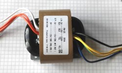
Looks easy enough.Need to ask, yes I did a search first, how do I hook up the primaries for 230V?
Black - neutral
Yellow - phase
Blue - not used
The theme song for wiring should be the old rock'n'roll hit "Let's Twist Again".
Well, either this, or power ground. Remember that the shield is supposed to keep primary-side E fields in check and eliminate capacitive coupling to the secondaries, and a Faraday cage relies on the shield being on a constant potential WRT your circuit. So if the circuit is already grounded from elsewhere (i.e. via the source) it won't make much difference, but with a floating source it might. So I would prefer power ground assuming there aren't any safety concerns.The screen I suppose goes to IEC GND?
Last edited:
Looks easy enough.
Black - neutral
Yellow - phase
Blue - not used
The theme song for wiring should be the old rock'n'roll hit "Let's Twist Again".
Well, either this, or power ground. Remember that the shield is supposed to keep primary-side E fields in check and eliminate capacitive coupling to the secondaries, and a Faraday cage relies on the shield being on a constant potential WRT your circuit. So if the circuit is already grounded from elsewhere (i.e. via the source) it won't make much difference, but with a floating source it might. So I would prefer power ground assuming there aren't any safety concerns.
"....like we did last summer"
Thanks. I will do some more research as hooking the primaries up the wrong way is potentially a transformer killer.
By power ground are you refering to mains gnd (ie) IEC-socket or cap bank gnd?
Unfortunenatly the only grounded outlets in my apartement is the ones in the kitchen, thus GND is floating between the equipment hooked up to the 6-way grounded extension chord I'm using by the PC.
Suppose I could hook up a groundwire to the radiator next to the PC (water pipes going in to the litteral ground)...but there's a small difference in the gnd potential. It can be felt as a tingeling feeling if touching the PC chassis and the radiator at the same time...
- Home
- Amplifiers
- Headphone Systems
- JLH Headphone Amp