Hi Grufti,
So sorry about that. I shipped the v1 out too soon before realizing the layout error on the DCDC converter footprint size. I can send you the updated boards when they come in, if you want. I’ll even throw in a set of the 6 opamps (4x opa1656, 2 Lme47924) for your trouble.
So sorry about that. I shipped the v1 out too soon before realizing the layout error on the DCDC converter footprint size. I can send you the updated boards when they come in, if you want. I’ll even throw in a set of the 6 opamps (4x opa1656, 2 Lme47924) for your trouble.
Last edited:
Stop Press!
Hi Folks,
I am sorry to tell you this, but there is an error on the BTSB board v1.1 and v1.2 and the SMT boards. When I built the verification board, I failed to test the SE outputs - I have been told by a member who contacted Jhofland and together, they determined that the phase on on the J36 connection is flipped. Having just ordered a new set of boards (now with this error), I will have to get a new set ordered and send out replacements to everyone who has already bought one. If you have not started populating them, you can wait for the new ones. Or if you have no need for SE out, you can go on as usual. There is a workaround by crossing some resistor legs on the TH board. The SMT board is not so easy as it requires cutting a trace and adding a jumper.
Please accept my apologies for this error, and I hope to send you replacements free of charge as soon as I get them in. Please PM me or send me a message in Etsy to confirm that your shipping address is still good, and how many boards your ordered.
It was the one thing I did not check, and of course I should know Murphy's law well by now.
Thank you,
xrl971
Here is the workaround if you have already populated your boards:
To fix the through hole version lift one end of R42 and of R43 and reconnect R42 to the pad for R43 and connect R43 to the pad for R42.
To fix the SMT board cut the trace from R35 & R39 to R47 at R47 and cut the trace from R42 to R46 at R46. Jumper from R35 & R39 to R46. Jumper from R42 to R47.
Last edited:
I would be very interested in a DC-powered finished version of this, enclosure and all.
Ideally with a non-powered fully passive connection-conversion-only mode, all possible combos between Balanced XLR and SE RCA
And using a Bypass button for those functions requiring power but disabling the active gain.
Sorry if my noob state makes this a foolish request, help me understand why.
Ideally with a non-powered fully passive connection-conversion-only mode, all possible combos between Balanced XLR and SE RCA
And using a Bypass button for those functions requiring power but disabling the active gain.
Sorry if my noob state makes this a foolish request, help me understand why.
To passively convert true baalnced line drive to SE requires a signal transformer. Trust me, a signal transformer will not be as neutral or as low distortion as state of the art OPA1656's. It will also be more expensive - look at Cinemags and Jensens.
You could do a "MacGyver" balanced to SE converter using some resistors, but that will probably require throwing away half of the signal and just using one side of the balanced. You would be negating all the self-cancelling noise reduction that the balanced line drive was supposed to provide.
From Rod Elliot's website on balanced line signals, here is a schematic of a Jensen JT-10KB-D signal transformer:
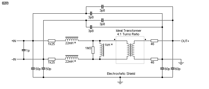
Last edited:
Bouncing off X's comments, check here for a passive SE->Bal alternative:
A Transformer-Coupled Balanced Output for Solid-State Preamps | audioXpress
The article includes performance measurements but to echo X's point, to get there is not a cheap exercise. As with all things in life, TANSTAAFL, YMMV and your ears will have to work out the pros/cons.
A Transformer-Coupled Balanced Output for Solid-State Preamps | audioXpress
The article includes performance measurements but to echo X's point, to get there is not a cheap exercise. As with all things in life, TANSTAAFL, YMMV and your ears will have to work out the pros/cons.
Thanks for that link Astromo. That particular Jensen converts SE to Balanced, I wonder if it works in reverse? The 0.002% THD at audio bands is quite impressive actually. You need to be careful where you locate the transformers as they can pick up hum from mains magnetic fields like a main power transformer. That was one of the biggest issues that I had with the Pass M2 amp is induced hum from the linear power transformer. Changing to a SMPS removed the source of the hum.
The JT-11-BMCF seems to be going for about $100 per channel, so that's $200 just for the pair of transformers. But it is a passive device.
The JT-11-BMCF seems to be going for about $100 per channel, so that's $200 just for the pair of transformers. But it is a passive device.
I understand not meant for HPs, current too low.preamp application meant to drive high impedance amplifier inputs
But isn't one of the main use cases for such a device,
even if zero/unity gain is fine
to lower the signal impedance so that is can more effectively drive the next stage (e.g. an amplifier) that is presenting **too low** an impedance?
I am planning to build a DC powered power amps from ICEpower 500A modules
and want to use balanced cabling when the distance between the signal source and the power amp gets too long.
This buffer amp design seems perfect for either or both applications?
please confirm.
If it was me, I'd orient the transformers at right angles to each other as an extra, cheap, easy method of noise pick up minimisation.
Shipping of Jensens outside the U.S. makes them even more expensive for people like me off in the antipodes. Just the way it goes.
The thought of going Bal->SE had crossed my mind but at the same time I thought that there must be some shortcoming with that plan that my limited knowledge is missing. Maybe not?
I understand not meant for HPs, current too low.
But isn't one of the main use cases for such a device,
even if zero/unity gain is fine
to lower the signal impedance so that is can more effectively drive the next stage (e.g. an amplifier) that is presenting **too low** an impedance?
I am planning to build a DC powered power amps from ICEpower 500A modules
and want to use balanced cabling when the distance between the signal source and the power amp gets too long.
This buffer amp design seems perfect for either or both applications?
please confirm.
Sorry I did not see this post - the LME49724 can drive relatively low impedance amp inputs. The datasheet says it can drive 600ohm load 3Vrms with 0.0003%THD.
https://www.ti.com/lit/ds/symlink/l...l-digikeymode-df-pf-null-wwe&ts=1600349659766
The SE output is driven by OPA1656, which has even more current capability, but ultimately limited by the onboard DCDC converter.
Like I said, I would not use these to drive headphones but any amplifier input should not be a problem for 600ohm capable opamp drive.
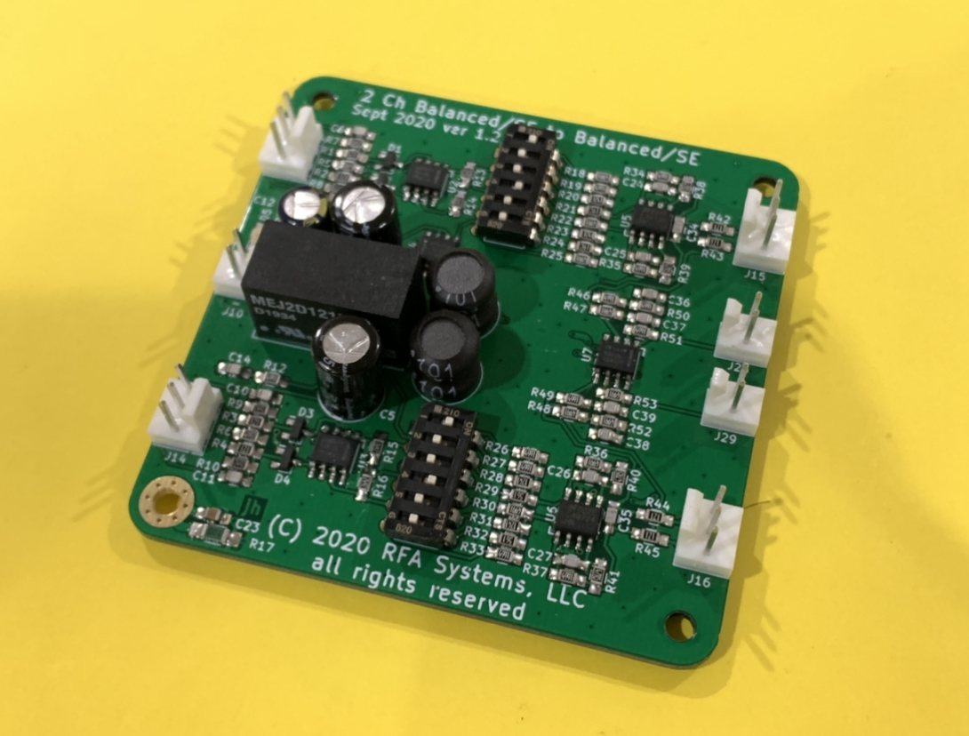
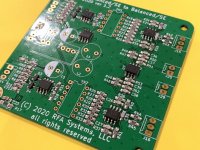
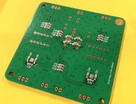
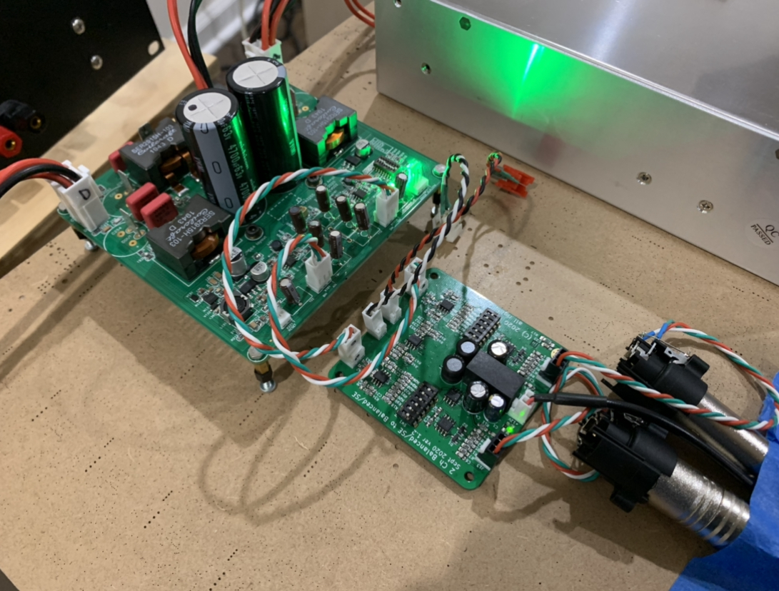
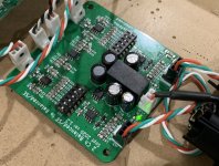
I finally got a chance to assemble the BTSB SMT v1.2. Will test tomorrow - need to assemble some Molex KK connectors between the source and the amp.
Solder paste applied with syringe and tapered plastic nozzle (blue one), hot plate on bottom and hot air pencil on top:
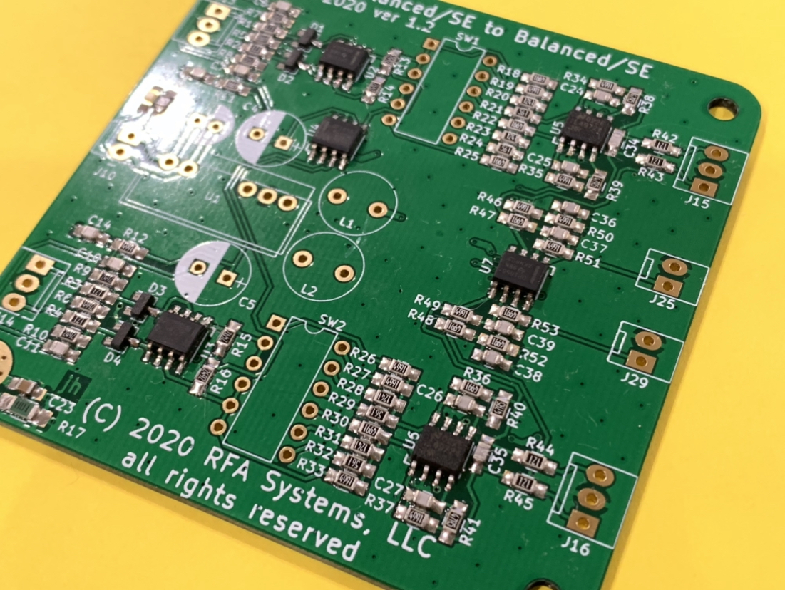
Bottom side has bypass caps all done with paste and hot air pencil:
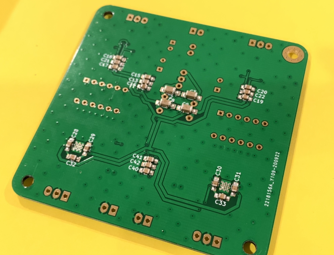
Then through hole parts were quick and easy:
A very enjoyable build.
Solder paste applied with syringe and tapered plastic nozzle (blue one), hot plate on bottom and hot air pencil on top:
Bottom side has bypass caps all done with paste and hot air pencil:
Then through hole parts were quick and easy:
A very enjoyable build.
Attachments

")
Hi Vunce,
Hopefully it fires up without any issues. As you pointed out, a 3-pin Molex KK can be inserted where the DCDC is and use an external PSU that provides +/-15v. However, I think that the built in Murata isolated DCDC and CLC (2.2uF 50v X7R / 100uH / 2.2uF 50v X7R) is a very quiet and effective combo. All it needs is 12v in from a Class 2 wall wart. Many SMPS have an auxiliary 12v supply output.
Hopefully it fires up without any issues. As you pointed out, a 3-pin Molex KK can be inserted where the DCDC is and use an external PSU that provides +/-15v. However, I think that the built in Murata isolated DCDC and CLC (2.2uF 50v X7R / 100uH / 2.2uF 50v X7R) is a very quiet and effective combo. All it needs is 12v in from a Class 2 wall wart. Many SMPS have an auxiliary 12v supply output.
The SMT BTSB has been tested with SE output (with FH9HVX) and Balanced output (with TPA3255). It works and sounds great. Totally transparent and very quiet when music is not playing. I also tested out the various gain settings using the DIP switch. It all works just as intended. Nice to ha e 0dB, 6dB, 14dB, AN’s 20dB on tap.

Attachments

- Home
- Group Buys
- BTSB Buffer - SE/Bal to SE/Bal Buffer GB