I just updated the listing to have two variations and each has two options.
Through Hole and Compact All-SMT variations.
Options are bare PCB and prepolulated SMT opamps. Although I think anyone choosing the SMT version will probably solder their own opamps.
BTSB Buffer SE/Bal to SE/Bal Buffer | Etsy
Through Hole and Compact All-SMT variations.
Options are bare PCB and prepolulated SMT opamps. Although I think anyone choosing the SMT version will probably solder their own opamps.
BTSB Buffer SE/Bal to SE/Bal Buffer | Etsy
Last edited:
Hi X again =),
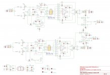
BTSB buffer looks very nice, however I have to make my own PCB where I am going to use THAT 1646. But when I look on your design I don't understand one thing.
Is R17 and C23 connected only with H2 in SMT version? Because in TH version it is connected with XLR connectors and H2, is it right? If yes, what is different in terms of input?
Sincerely
Petr Petlach
For TH or SMT version, if you want to drive it with SE input, you need to connect the +ve input to the signal and -ve input to ground. This can be achieved using an XLR combo input jack like the one in the BOM of the TH version and use a 1/4in mono TS plug such that the "ring" and the "sleeve" are grounded to each other and the "tip" goes to +ve input. They make RCA female to 1/4in TS plugs, they are very handy.
Here is what I use:
Amazon.com: Hosa GPR-101 RCA to 1/4 inch TS Adaptors (2 pieces), Black: Musical Instruments
Here is what I use:
Amazon.com: Hosa GPR-101 RCA to 1/4 inch TS Adaptors (2 pieces), Black: Musical Instruments
Not yet. You don’t believe that two state of the art opamps will give THD below that measurable by conventional DIY gear?I’ll give it a measure when I get some time. Basically a loop back test with the unit in series acting as a “cable”.
I do. But other "things" can go wrong..
//
Measurements of BTSB
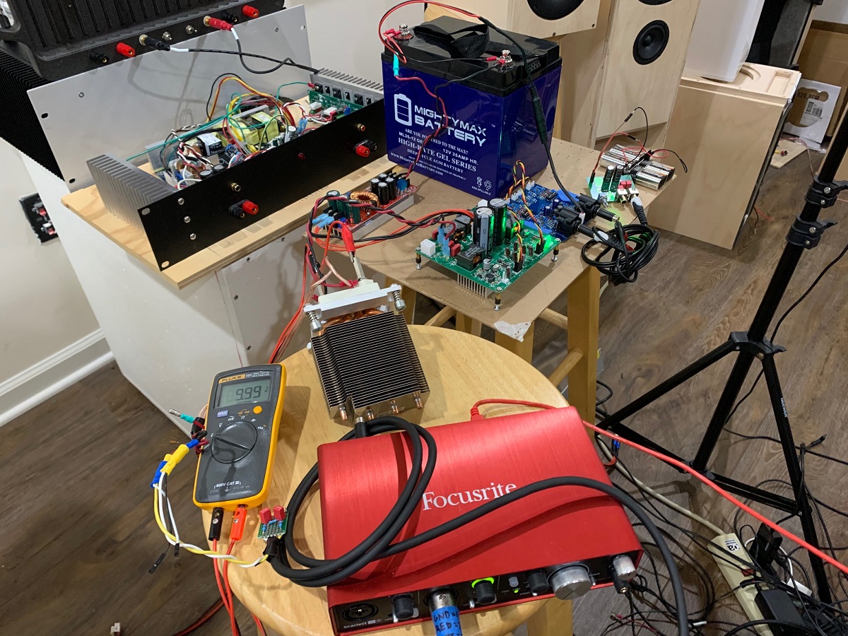
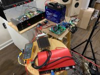
This was a lot of work, but in the end - worth it to prove to myself that the BTSB is a superb buffer. I setup the TPA3255 to be powered from a 12v lead acid battery driving an 800w DC-DC converter (51v). The battery also provides the 12v to power the BTSB DC input. The 1kHz low noise Victor's oscillator is also powered by 4x9v batteries. Laptop (HP Core i7 Pavillion) was powered by its own battery and laptop USB powers the Focusrite. This was the best way to get myself off the dirty nasty grid around my house. Just touching the ground/earth mains gives ugly noise in the measurement. Here is a photo of the setup:
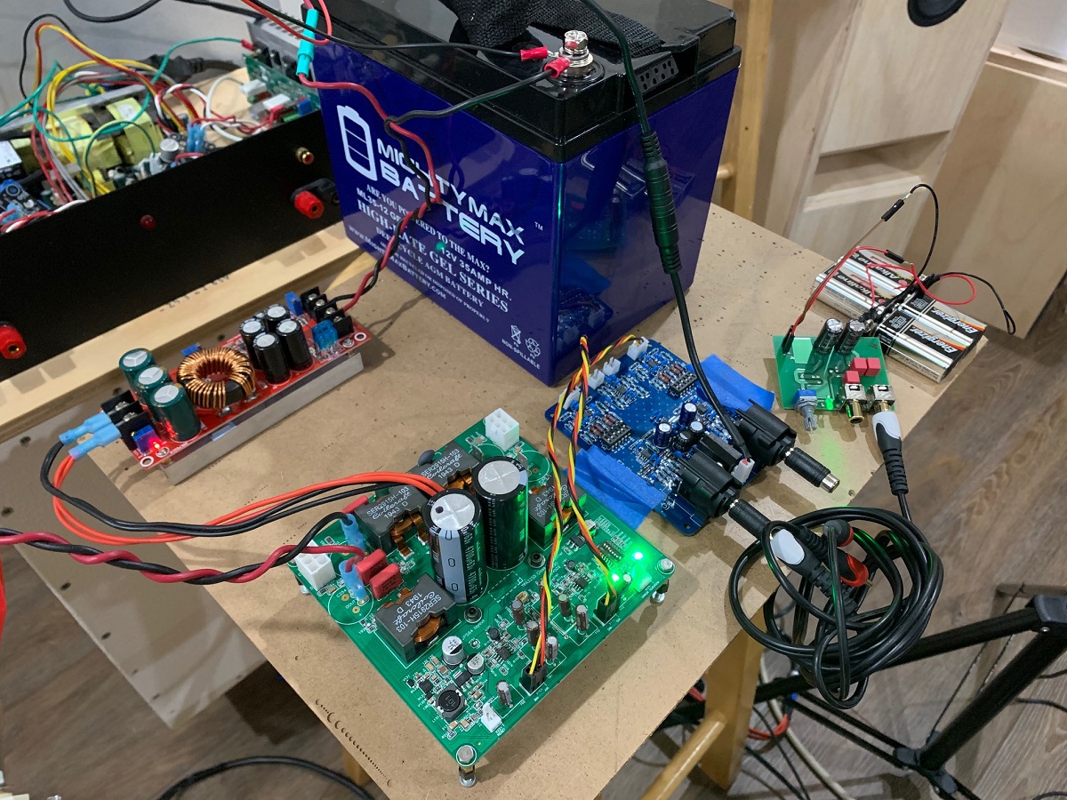
A closeup of the BTSB, amp and DCDC:
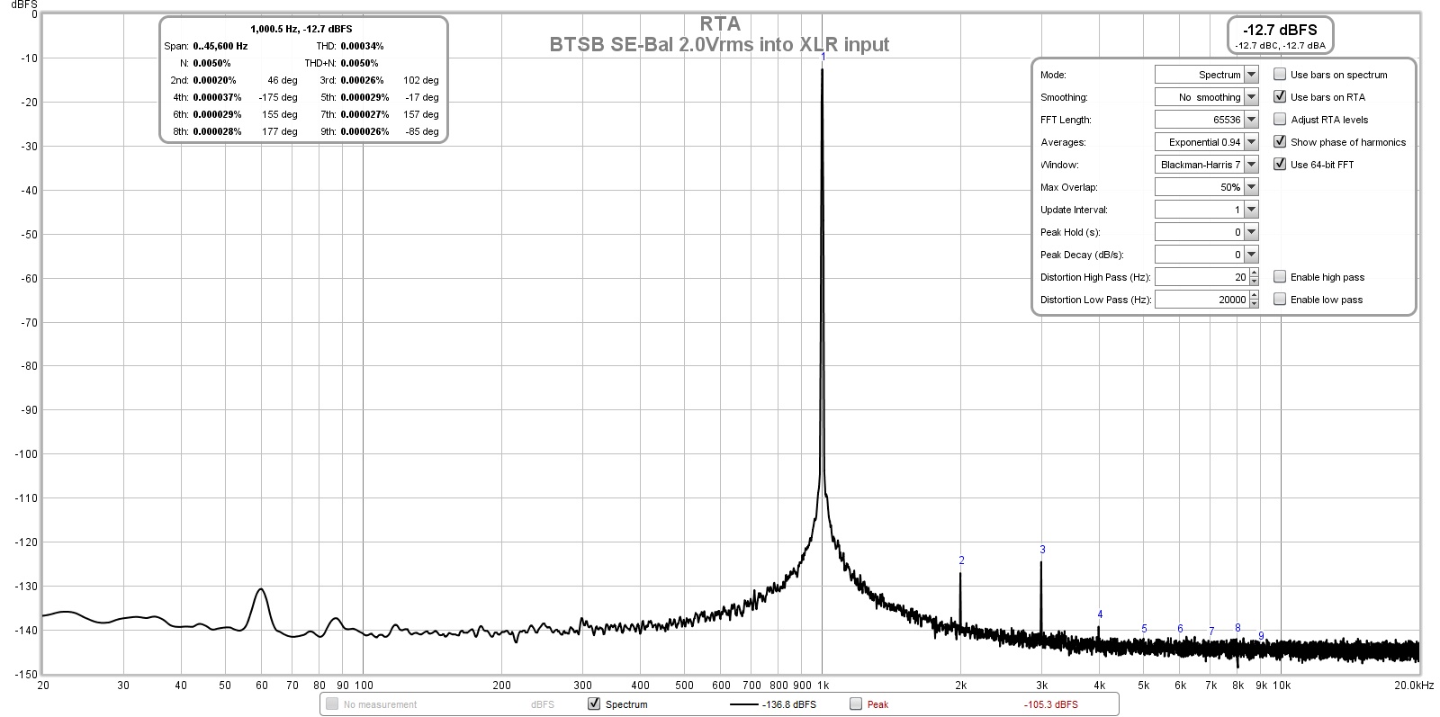
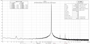
Here is the FFT for BTSB connected to the Focusrite's XLR input (instrument mode impedance - high impedance) and the BTSB was set to 20dB gain and putting out 2.0Vrms. The level of disortion here (0.00034%THD) is probably the Focusrite's internal distortion as we are already below the device's published ratings:
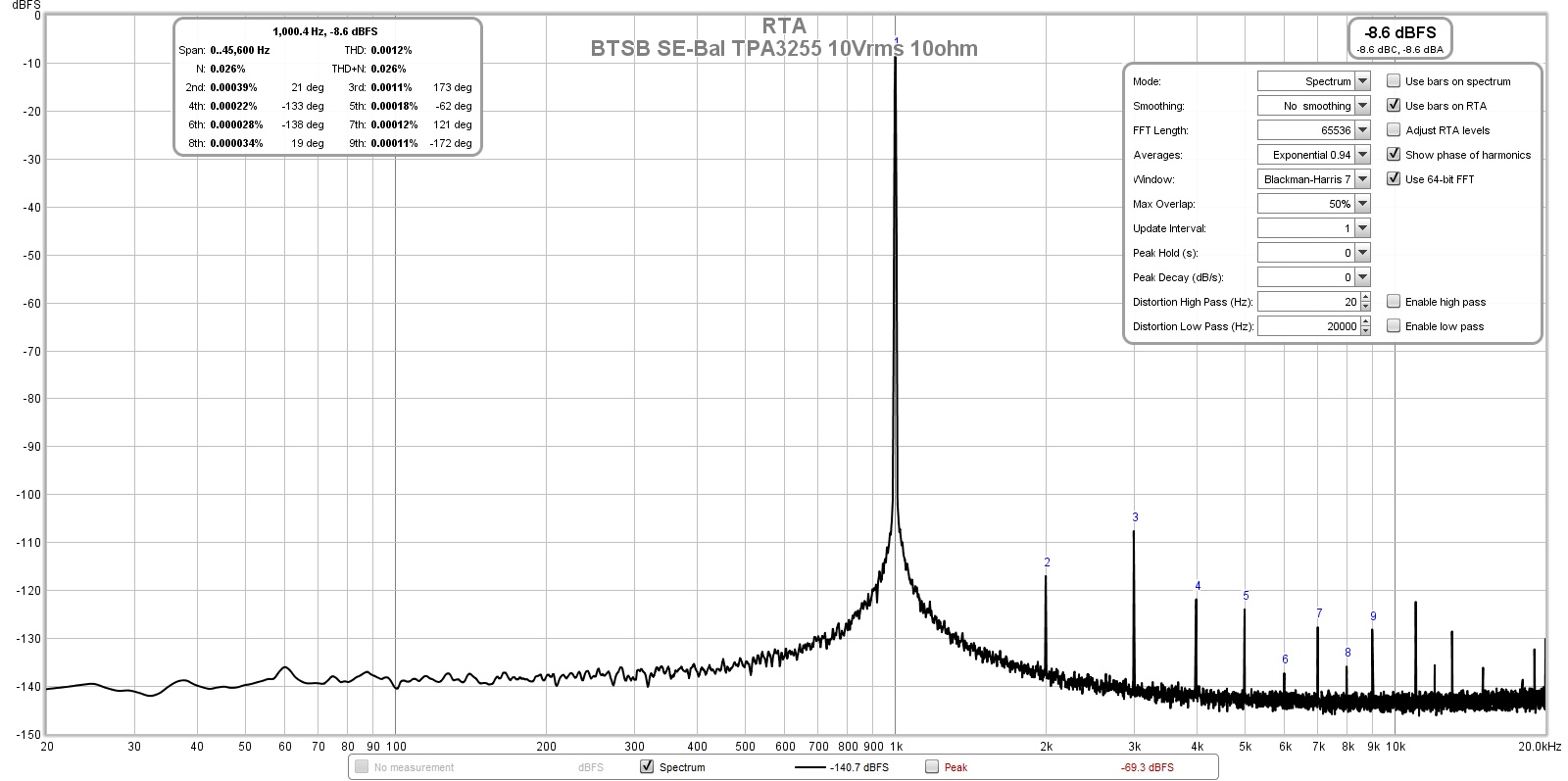
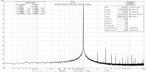
Here is the FFT for the BTSB in SE to Bal driving the TPA3255 with PFFB and at the reference 10Vrms into 10ohm condition. It is getting 0.0012% THD, well below the TI factory spec for the same reference condition with their own PFFB implementation. It is about the same as the previous 0.0011% THD that I measured using the THAT1646 SE to Bal converter. However, the noise profile now is cleaner with less HF "grass". The amps are different units so there is some variability to be expected. The previous one tested has been sold:
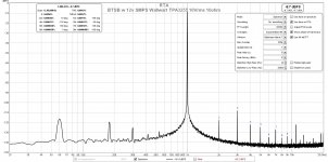
For completeness, here is what the BTSB powered with a cheap 12v 1A SMPS wallwart - it adds a little more noise at 60/120/180Hz, but still a respectable noise floor and THD and harmonic profile stays the same:
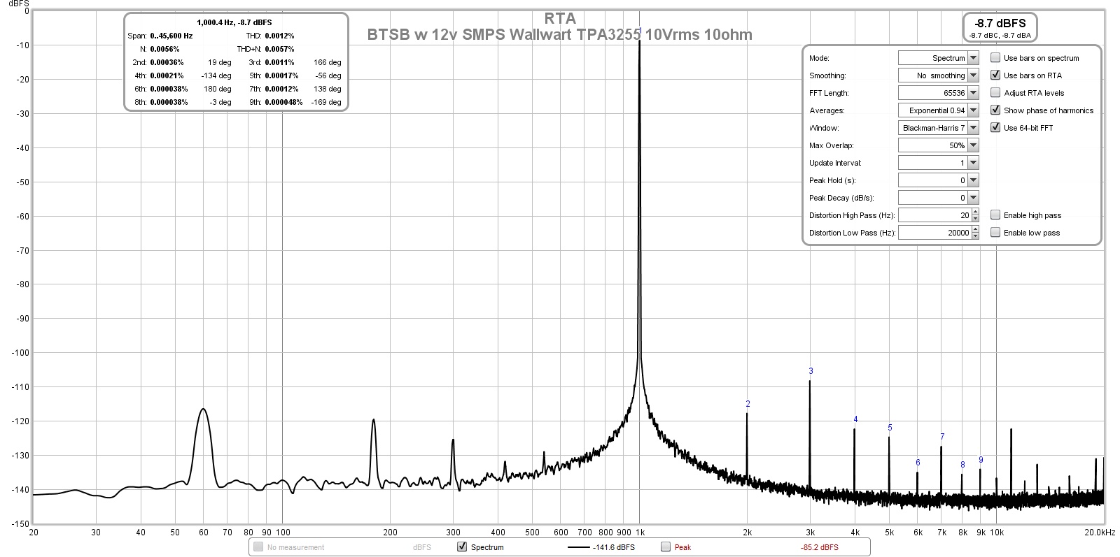
So I think we can see that this design is excellent and does what it is supposedd to do - not add any noise or distortion to the signal.
This was a lot of work, but in the end - worth it to prove to myself that the BTSB is a superb buffer. I setup the TPA3255 to be powered from a 12v lead acid battery driving an 800w DC-DC converter (51v). The battery also provides the 12v to power the BTSB DC input. The 1kHz low noise Victor's oscillator is also powered by 4x9v batteries. Laptop (HP Core i7 Pavillion) was powered by its own battery and laptop USB powers the Focusrite. This was the best way to get myself off the dirty nasty grid around my house. Just touching the ground/earth mains gives ugly noise in the measurement. Here is a photo of the setup:
A closeup of the BTSB, amp and DCDC:
Here is the FFT for BTSB connected to the Focusrite's XLR input (instrument mode impedance - high impedance) and the BTSB was set to 20dB gain and putting out 2.0Vrms. The level of disortion here (0.00034%THD) is probably the Focusrite's internal distortion as we are already below the device's published ratings:
Here is the FFT for the BTSB in SE to Bal driving the TPA3255 with PFFB and at the reference 10Vrms into 10ohm condition. It is getting 0.0012% THD, well below the TI factory spec for the same reference condition with their own PFFB implementation. It is about the same as the previous 0.0011% THD that I measured using the THAT1646 SE to Bal converter. However, the noise profile now is cleaner with less HF "grass". The amps are different units so there is some variability to be expected. The previous one tested has been sold:
For completeness, here is what the BTSB powered with a cheap 12v 1A SMPS wallwart - it adds a little more noise at 60/120/180Hz, but still a respectable noise floor and THD and harmonic profile stays the same:
So I think we can see that this design is excellent and does what it is supposedd to do - not add any noise or distortion to the signal.
Attachments
-
 BTSB-SE-Bal-TPA3255-testing-setup.jpg422.2 KB · Views: 1,145
 -
 BTSB-SE-Bal-TPA3255-testing-setup-closeup.jpg446.1 KB · Views: 1,164
 -
 BTSB-SE-Bal-2Vrms-Loopback-FFT.jpg232.2 KB · Views: 6,807
 -
 BTSB-SE-Bal-TPA3255-10Vrms-10ohms-FFT.jpg232.4 KB · Views: 8,706
 -
 BTSB-SE-Bal-TPA3255-10Vrms-10ohms-FFT-wallwart.jpg237 KB · Views: 1,138
Here is the Mouser shopping cart for the BTSB TH BOM:
Mouser Electronics
Here is the shopping cart for the BTSB Compact SMT BOM:
Mouser Electronics
If you use these, please save as your own project before modifying them.
Thanks to Vunce for putting these together!
Mouser Electronics
Here is the shopping cart for the BTSB Compact SMT BOM:
Mouser Electronics
If you use these, please save as your own project before modifying them.
Thanks to Vunce for putting these together!
Due to popular demand, I have just about run out of stock of the initial set of BTSB v1.2 TH boards. I just ordered more last night and also ordered the revised SMT compact version 1.1. Should be here in 7-9days.
Thanks for your patience and for the great show of interest.
Thanks for your patience and for the great show of interest.
- Home
- Group Buys
- BTSB Buffer - SE/Bal to SE/Bal Buffer GB