No prob Aljordan!
We’re all ok, hopefully that’s the way it stays 🙂
@GaryS
Guinness Time for me 😀

We’re all ok, hopefully that’s the way it stays 🙂
@GaryS
Guinness Time for me 😀
Showing your Irish blood Vunce - just about to knock the top of a chilled IPA beer here at 3pm Sunday afternoon.
Look forward to the BOM when you post it here.
Keep your head down and stay safe there in NY.
Cheers
Gary..
Look forward to the BOM when you post it here.
Keep your head down and stay safe there in NY.
Cheers
Gary..
Hakuin M2x Mouser Cart
Here’s the Mouser cart for the new Hakuin M2x daughter board.
Resistor values for optional Toshiba Jfet/BJT devices are included.
V102 is non-stocked and therefore not included in the cart. It will have to be sourced elsewhere until Mouser get them in.
This cart is for a single board, multiply as necessary.
Mouser Electronics
https://www.diyaudio.com/forums/att...class-hp-amp-hakuin-m2x-schematic-2sa1837-jpg
Last edited:
Thank you, Vunce!
$16.45 for a BOM is not bad at all! The 2SK209BL's when in stock were about $0.45ea. 🙂
$16.45 for a BOM is not bad at all! The 2SK209BL's when in stock were about $0.45ea. 🙂
The Toshiba 2SK209BL's might be a big problem. Mouser is not showing any future delivery time scale at all and Digikey is quoting at least 52 weeks lead time!
Anyone have a clue as to who might have them in stock (apart from dodgy Asian sources that is)- not that I need them as I will use the 2SK170BL's. May help other builders though.
An ebay search shows outrageous prices!!
Anyone have a clue as to who might have them in stock (apart from dodgy Asian sources that is)- not that I need them as I will use the 2SK170BL's. May help other builders though.
An ebay search shows outrageous prices!!
Last edited:
Mouser has 20,800 GR’s in stock.
2SK209-GR(TE85L,F) Toshiba | Mouser
Let me rerun sims - should work though as these are capable of 14 mA. We only need 5mA to 6 mA.
2SK209-GR(TE85L,F) Toshiba | Mouser
Let me rerun sims - should work though as these are capable of 14 mA. We only need 5mA to 6 mA.
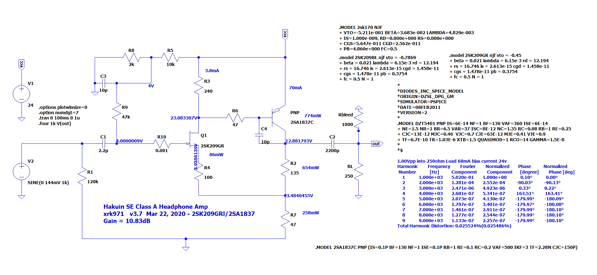
An LTspice model for the 2SK209GR is not available, but I talked to Keantoken who said that it is close enough in shape of response to BL, just vary the Vto value in the model to drop the Idss down. So I changed it manually to get aboiut 4mA Idss vs 7mA Idss of the BL. This resulted in the following resistor setpoints that changed: R3=240ohms, R4=100ohms. This gives about 10.83dB gain and similar harmonic profile and THD values as with the BL. So now we can go crazy and buy 100 tape roll of the GR's for21.5 cents ea. You will have enough for many projects to come.
Attachments
Thanks JP, I have the Toshiba 2SK170BL's here- so I am fine.
Other members will need to use the LS types or as X has posted the GR version of the 2SK209.
Other members will need to use the LS types or as X has posted the GR version of the 2SK209.
So to keep busy during this spare time, I went to work on the Hakuin M2x boards. I used the exact Mouser cart from post# 1224. Since these Hakuin modules will be used strictly for preamp duty in the Yarra, I eliminated a few redundant components the main board already has. I used the adjusted resistor values for an all ‘Vintage’ Toshiba edition. (Right on GaryS 😀)
Yarra rail voltage is 28.5vdc feeding the Hakuin, after its onboard CRCRC the voltage drops to 24.5vdc. Voltage across R112 is 11.9v, that’s good for a tick under 80mA bias. I strategically placed a few components on the underside of the pcb to allow clearance for the 2SA1837 heatsinking and to give R121 room to breath, it gets a bit warm.
C113 and C114 were not populated at first because the Yarra main board is cap coupled. But, I noticed a slight DC spike when powered on and off. Installing a 5uF film cap in C114 totally eliminated the DC spike and offset is now rock solid hovering at 0mV.
First listening impression is this circuit is extremely quiet with a deep black background. The Yarra/Hakuin preamp combo is now in my main system so it will be getting a heavy workout in the coming weeks 😀
Attachments


Nice work Vunce, what type of capacitor is the 5uF / 50VDC you have used?
Would be interested in how it sounds after a few hours burn in.
Did you measure the Idss of the 2SK170BL by any chance before soldering it in?
Would be interested in how it sounds after a few hours burn in.
Did you measure the Idss of the 2SK170BL by any chance before soldering it in?
Note that depending on the value of the bleed resistor you are driving, a 5uF cap at C114 will have a bass extension response equal the 1/0.7RC time constant. A 5uF cap negate any big 2000uF cap you have downstream in the main board to nominally, about a 5uF cap value.
DC drift without the 5uF cap just means that the time constant of the large cap is so big, it drifts over time due to the bleed off resistor being slow. You want that time constant to be of order 1/10second or 10Hz.
Assuming a 1kohm bleed resistor and 5uF cap, that will have a 185Hz for a -3dB point. You will notice soft rolled off bass.
I would suggest at least 100uF cap for 1k bleed resistor to make sure -3dB is at 12Hz.
But if your bleed resistor is 10k then you have 29Hz F3.
I think that maybe the best thing to do is have no output caps on the main board and let the daughterboards each handle AC coupling in their own. That way, DC coupled amps like Melbourne and WB18 can run unfettered by any cap induced bass fall-off.
Last edited:
My all around recommendation is 1000uF audio grade like Silmic, your favorite 2.2uF to 4.7uF film cap like a Wima MKP or even a Mundorf film in oil cap. That should be swell.
DBs for the F6 front end buffer
Hey all. One of the chaps over on the F6 build guide thread is using a mod'd Austin DB in place of the Toshiba Jfet input buffer. I was wondering if I could rig my F6 to use the DBs that I have for the M2X and the Yarra? I know that these all have been designed to be compatible with the M2X. Being a bit of a noob, I'm not sure how to figure out if the DB's will work with the F6. I'm not a fan of the magic smoke, but I do tend to lean towards the FAB side.
Post #1726
F6 Illustrated Build Guide
I have a plan how to do this, but if I have to mod the circuit to make each DB to work, it might not be worth it.
I did a little digging. It looks like the F6 and M2 input buffers are nearly the same. The M2 has R3-10R and R4-10R between the Jfets and the transformer, but the F6 does not.
The M2X dose not have R3 and 4 on the main board, but are on some of the DBs. The transformers for both amps have a 600R input impedance. But the output is 600R for the F6 and 15K for the M2X.
Are R3-4 in there to lower the signal level from the Jfets to the transformer in the M2 design? If I read it right the M2 transformer is the voltage gain stage for the amp. So my guess is that R3-4 are to lower the gain from the Jfets, and not over drive the output stage. This probably designed into the M2X DBs as well. If that is the case, the F6 must not need R3-4 in there to lower the gain from the Jfets.
I'm willing give it a try, but just don't want to let the smoke out. I'm still learning a lot from you all, and any input would great!
Hi Tbone,
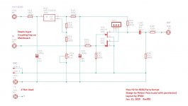
The F6 topology looks quite a bit different in that the JFET front end drives two windings of the signal trafo in a balanced push-pull configuration rather than in SE Class A like the M2. And there is negative feedback to the signal trafo. Sort of an F5 with a signal trafo for voltage gain. It does not look so simple to put a Yarra DB on the front of the F6. Maybe Hugh can give some advice, but I do not see an "Easy" implementation.
Here is F6:
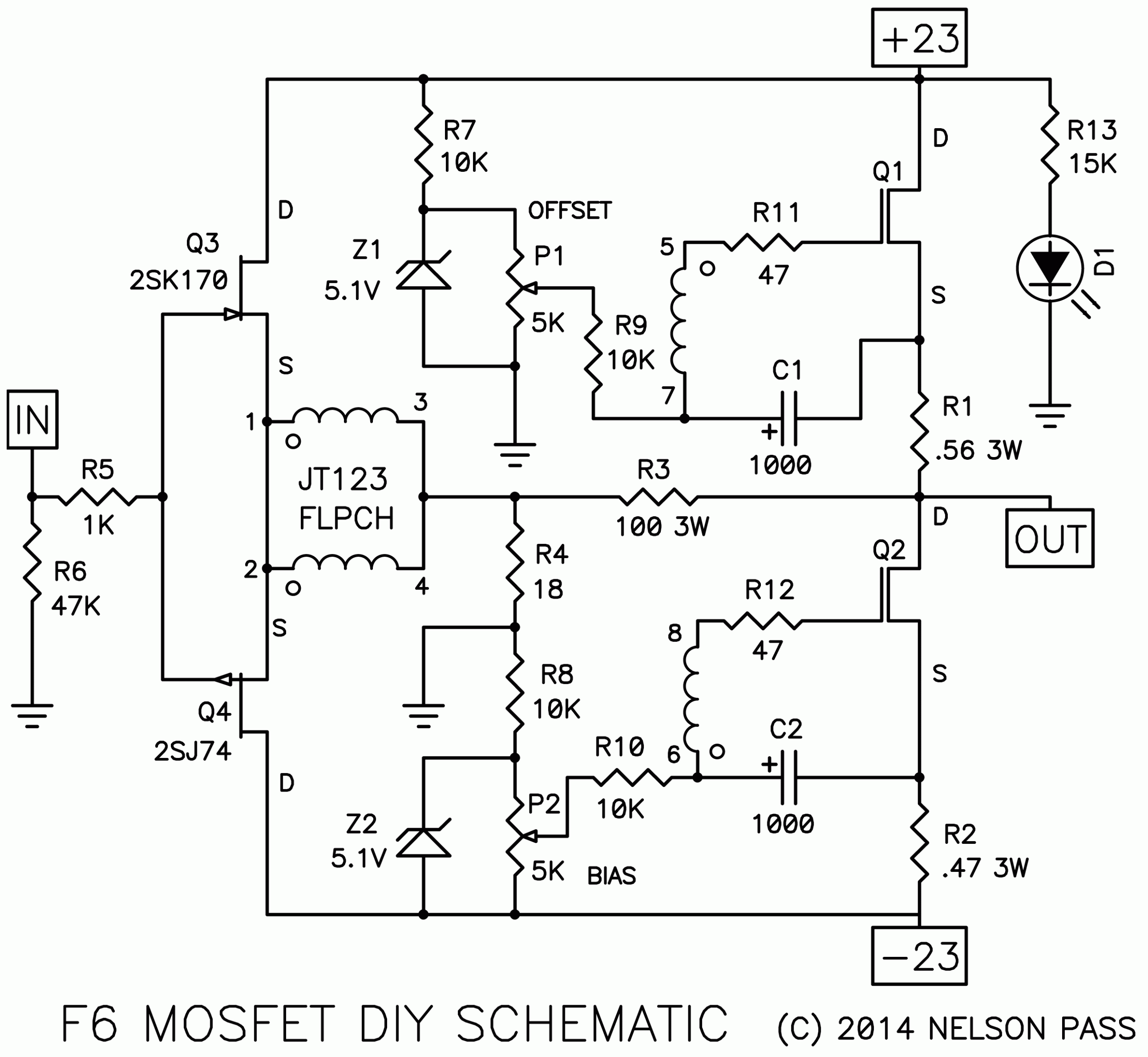
Here is the M2X:
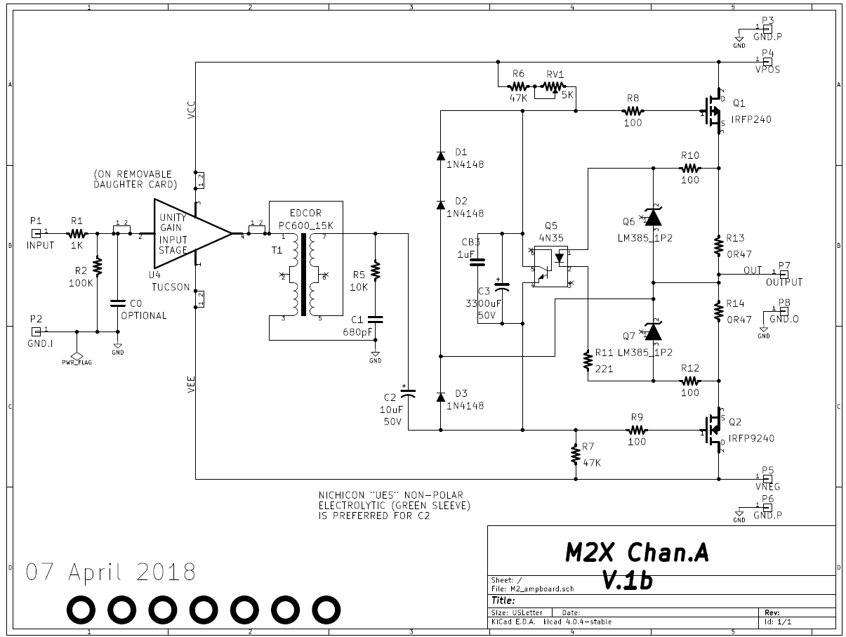
If anyoen else has suggestions on how to make it work, please chime in.
The F6 topology looks quite a bit different in that the JFET front end drives two windings of the signal trafo in a balanced push-pull configuration rather than in SE Class A like the M2. And there is negative feedback to the signal trafo. Sort of an F5 with a signal trafo for voltage gain. It does not look so simple to put a Yarra DB on the front of the F6. Maybe Hugh can give some advice, but I do not see an "Easy" implementation.
Here is F6:
Here is the M2X:
If anyoen else has suggestions on how to make it work, please chime in.
Pass H2 implemented in Yarra/M2X compatible format
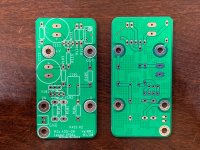
JPS64 designed the Pass H2 circuit (with Mr. Pass' permission) and here are the boards - just arrived from the factory. I soaked them in diluted-bleach water and detergent for 5 minutes and dried before touching them 😀
The Gerbers are freely available for this project (send JPS64 a PM if you are interested).
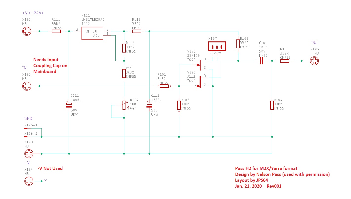
Schematics:
https://www.diyaudio.com/forums/attachments/pass-labs/824852d1584173707-h2-h2-m2x_sch_001-pdf
Stuffing Diagram:
https://www.diyaudio.com/forums/attachments/pass-labs/824853d1584173707-h2-h2-m2x_pba-top_001-pdf
JPS64 designed the Pass H2 circuit (with Mr. Pass' permission) and here are the boards - just arrived from the factory. I soaked them in diluted-bleach water and detergent for 5 minutes and dried before touching them 😀
The Gerbers are freely available for this project (send JPS64 a PM if you are interested).
Schematics:
https://www.diyaudio.com/forums/attachments/pass-labs/824852d1584173707-h2-h2-m2x_sch_001-pdf
Stuffing Diagram:
https://www.diyaudio.com/forums/attachments/pass-labs/824853d1584173707-h2-h2-m2x_pba-top_001-pdf
Attachments
Last edited:
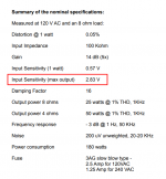
The F6 transformer datasheet is HERE and the F6 owner's manual includes a table of measured specifications, on page 10.
_
_
Attachments
- Home
- Group Buys
- The YARRA Preamplifier/HPA for Melbourne DB Group Buy