Hi X and others,
Got around to some testing on the Yarra psu with no load. The voltage wrtg on the 4 - 2R2 resistors was 34.5 V. I am using the Talema 22V.
With the trim resistor's dialed to maximum drop, the output voltage for each rail was as follows:
LS+ = 29.4V, LS- = 28.4V, RS+ = 29.4V, RS- = 28.4V
I believe that psu is operating correctly (I am asking) and will set the trim resistor for a +/-29V drop and continue work / testing on the main board amplifier.
Thanks for comments,
MM
Hi X and other builders. Kind of a mystifying day in the electronics lab.
1. I adjusted the 4 trim pots to around the mid-pt. I then attached the ribbon cable from the Yarra psu to the Yarra MB. I also attached a DMM to the test points on the Melb DB to check the bias. I also connected another DMM to the +V and -V wrt ground so I could adjust the trim pots. I powered up and let it warm up. No smoke, foul ouders, all led's shining.
2. Adjusted trim pots to lowest setting and read from left side of Yarra psu: =28.6V, -28.6V, +30.1V, -28.8V
3. Checked bias on right side DB, fluctuated between 90 and 100 mv. Watched for a while, but just fluctuated around the values. The left side DB bias was instantly a solid at 441mv.
4. Thought I would adjust the trim pots to be the same at +/- 30V and check bias again: The right side bias started at 155mv and over the course of 1 hour reached a max value of 400mv. The heatsink were warm, but I could touch them for around 30 seconds or more. The left side DB instantly showed 439.7 mv bias and I could only touch the heatsinks for about 5-6 seconds.
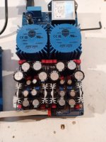
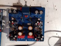
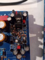
Please see the attached pics, hope they might show something. Once I hear back with any ideas, I wll go through the routine of checking resistor values& making sure in the correct places, checking solder joints, checking transistor orientation, etc.
Thought I had it made with the readings from the first two trim pots. 🙁
MM
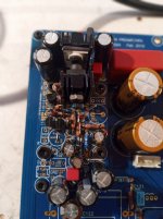
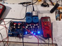
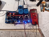


Hi Myles,
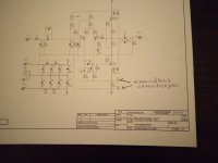
Can you tell me where you are measuring the bias that varies from 155mV to 400 mV? Reference markup image of schematic would be best. Is this the class A bias current across the output devices?
Can you tell me where you are measuring the bias that varies from 155mV to 400 mV? Reference markup image of schematic would be best. Is this the class A bias current across the output devices?
Ok, 150mV to 450mV across an 8.2ohm resistor says that current is 18.3mA to 55mA. It has been a while, but I seem to recall that the Class A bias current that I was aiming for was in the 40mA range. Power dissipation would be 0.040A x 29v or about 1.16W. That’s about right for the screw on flag heatsink on the output device.

I think it’s normal to only be able to touch a hot 1.2W TO-126 BJT for 3-5seconds.
Check R123 and R124 to make sure the values are correct. It should be running about 40mA to 50mA of bias current.
I think it’s normal to only be able to touch a hot 1.2W TO-126 BJT for 3-5seconds.
Check R123 and R124 to make sure the values are correct. It should be running about 40mA to 50mA of bias current.
Thanks X,
I will check out the R123 and R124 resistors. Are you not concerned that the bias took so long to get up to 400mV, or is that what the resistor check is for? Thanks for the help.
MM
I will check out the R123 and R124 resistors. Are you not concerned that the bias took so long to get up to 400mV, or is that what the resistor check is for? Thanks for the help.
MM
Hi X,
On the Melbourne DB's, I checked all the resistors, correlating them with the color codes and checked all the brown Dale resistors also. I checked the DNS2025 and the KSA1381 transistor for proper positions on the DB's. I reflowed all the solder joints. Everything seems fine, but the bias voltage readings are suspect.
I am going to start at the beginning and trace voltages through the Yarra psu circuit. So in that regard, I have the 22V Talema's and I have installed the voltage selector which is set to 115V. Please see pics of upper part of psu along with the schematic and stuffing pics.
My understanding is that the rectified voltage at the 2R2 resistors R155,R156,R175,R176 should be 22V x 1.414 = +/-31VDC. I am measuring +/- 35V at the downstream side of the 2R2 resistor. I am at a loss as to why I have an extra 4VDC at the 2R2 resistors. Help is always appreciated.
MM
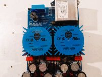
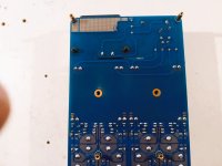
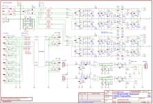
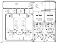


Hi,
Any Yarra/Melbourne DB builders have any idea's to start me on my journey as to why I am seeing an extra +/- 4V at the 2R2 resistors on the Yarra psu as mentioned in post #1648 above?
Thanks,
MM
Any Yarra/Melbourne DB builders have any idea's to start me on my journey as to why I am seeing an extra +/- 4V at the 2R2 resistors on the Yarra psu as mentioned in post #1648 above?
Thanks,
MM
Can you connect some dummy loads to draw some current and we will see what the voltages are like.
Use some 600ohm 5W resistors. Connect one to +v out and GND and other -v out and GND. This should be circa 50mA current load and about 1.5W dissipation.
The voltage after the 2R2 resistor will depend on that the regulation transistors are doing and that will change the current flowing through them.
If the voltage on one trafo is different than the other one, there is a load drawing heat somewhere. It may be going to one of the heatsinks in the regulator transistors. Are they warmer on the lower voltage PSU channel?
Thanks for the info. I can do all the tests that you describe above. One answer that I can comment on is that all the heatsinks felt like they were all the same temps. The concept that I am not grasping is why the DCV at the 4 x 2R2 resistors does not reflect 31V rather than the 35V I measured wrtgnd.
Could my diodes be faulty ?
Should the voltage at R153, R154, R173, R174, the resistors at the transformer outputs / above the diodes be measured AC or DC on the DMM and what should I expect as a measurement.
Thanks again for the help,
MM
Could my diodes be faulty ?
Should the voltage at R153, R154, R173, R174, the resistors at the transformer outputs / above the diodes be measured AC or DC on the DMM and what should I expect as a measurement.
Thanks again for the help,
MM
Hi Myles,
Check the AC voltage at the transformer secondaries.
If your mains voltage is on the high side, say 125V, that would yield a higher transformer secondary voltage like 23.5V.
This would contribute to a higher than expected DCV after rectification.
Check the AC voltage at the transformer secondaries.
If your mains voltage is on the high side, say 125V, that would yield a higher transformer secondary voltage like 23.5V.
This would contribute to a higher than expected DCV after rectification.
- Home
- Group Buys
- The YARRA Preamplifier/HPA for Melbourne DB Group Buy
