Hi ryanj,
So I am a bit of an audio dinosaur, I love good vinyl and my digital audio is a Shigaclone Black MKII I built. I have spdif out. Currently I use either the Subbu DAC or a dual TDA1543 design built from Peter Daniels. I plan on building the D3 X 2 1541. Can I supply WS, BCK, and D from CS8412 to your I2S sim pcb? I also can add 80mhz asynch reclocking IC in signal path between 8412 and sim brd. Tube amps/ Pass pre / LaScala type DIY components in system. Thanks for advice.
regards,
Steve
Hi Steve,
If the CS8412 outputs 2's comp LSB justified data, then it should work just fine. There is also the Sony I2S format, which im not sure will work on the convertor board or not.
What output stage are you thinking for the D3? At the moment im trying out something similar to Laszlo's Valve Output Stage Laszlo's Valve Output Stage with Lundahl transformer only difference I have the transformer in voltage mode using 1.7R IV resistors, still playing around tuning the circuit but at the moment h2 and h3 are below -90db with about 900mVpp output, and the DAC sees about 6.8mVpp with the 1.7 ohm IV resistors in place. At the moment im using the sowter 1465 but will also try the LL 1678 soon with a few different tubes and output caps.
Good luck with the D3 build
I should be able to as long as I set M0-M3 right, also forgot I have twisted pear WM8804 and their CS4816 4:1 mux receiver which do I2S. MY problem now is parts!!! Some are out to July 2022.
I have been following the transformer output stage threads at this time I am open and have sometime [parts] to decide!
best regards,
Steve
I have been following the transformer output stage threads at this time I am open and have sometime [parts] to decide!
best regards,
Steve
Hi Steve,
I think a transformer output stage can sound good but I mistakenly had the expectation of getting line level output with low THD from a single transformer stage, when in reality this doesnt seem to be possible. Also, having a dominant H3 isn't particularly nice sounding unless its below at least -85dbc. I found that when running the DAC in balanced mode with the cancelation of H2 it is benefitial to have a very low output from the transformer to minimise THD and also add a little bit of H2 back with a tube circuit.
One other thing is the IV resistor, so far I prefer the IV resistor on the DAC output/primary winding with the sowter 1465. When the IV is on the secondary there is very high impedance to a full scale current sample spike resulting in a massive voltage spike on the DAC output, I supose this is a limitation of the transformer bandwith. This might be the reason why I prefer IV on the primary side with the sowter. Other transofmers like Ivans have a higher bandwidth so I dont think this is as big of an issue.
I hope you eventually get your parts!
Hi Ryan,
Hi everybody!
Overall, seems you get the right conclusions. Ryan you have brought up an important topic, let me also react and add. I can conclude as well that for the successful operation of the transformers, it is necessary to use resistors on both sides of the transformer, this will linearize the operation of the transformers themselves and allow you to get the best result. However, for a long time I was not satisfied with the presence of a resistor in the primary coil. Why? Because the quality of this low impedance resistor becomes DECISIONAL for the sound, the overall quality and timbre / color / signature are all different. The specific type of resistor and its value is the basis of the sound. Moreover by using a resistor in the primary as well, the type of high-valued resistor in the secondary becomes audible (in my trafos, at least). Foil, tantalum / niobium, and wire types gives a good results. But taking into account that such resistors are not cheap ($10-60) however, the best results have been obtained using my own manganin (wirewound) resistors.
Next, regarding the signal level. I can try to explain for a long time based on THD, but in fact, everything automatically becomes in its best place (better sound quality) when the sound bandwidth becomes 2Hz-110kHz (-3dB points). There is no need to talk about any line levels when using one only transformer, even when using 4 chips - it is impossible without active circuits. If you want a line level from one chip and one transformer - take ES9038PRO with its huge signal output power (30x times more than 1541). But if you still want 1541A, then the two-stage (at least) principle only with active components. Given this bandwidth, my reality (one TDA1541A-S2) is this: resistor-> transformer-> current buffer-> transformer-> current buffer. And I am at 0.4Vrms only after that . Otherwise, without the use of active amplifying stages, it is simply impossible to reach the level in line (0.775V) range of the output signal at the required bandwidth (read the required quality level). That is my 50 cent.
Hi everybody!
Overall, seems you get the right conclusions. Ryan you have brought up an important topic, let me also react and add. I can conclude as well that for the successful operation of the transformers, it is necessary to use resistors on both sides of the transformer, this will linearize the operation of the transformers themselves and allow you to get the best result. However, for a long time I was not satisfied with the presence of a resistor in the primary coil. Why? Because the quality of this low impedance resistor becomes DECISIONAL for the sound, the overall quality and timbre / color / signature are all different. The specific type of resistor and its value is the basis of the sound. Moreover by using a resistor in the primary as well, the type of high-valued resistor in the secondary becomes audible (in my trafos, at least). Foil, tantalum / niobium, and wire types gives a good results. But taking into account that such resistors are not cheap ($10-60) however, the best results have been obtained using my own manganin (wirewound) resistors.
Next, regarding the signal level. I can try to explain for a long time based on THD, but in fact, everything automatically becomes in its best place (better sound quality) when the sound bandwidth becomes 2Hz-110kHz (-3dB points). There is no need to talk about any line levels when using one only transformer, even when using 4 chips - it is impossible without active circuits. If you want a line level from one chip and one transformer - take ES9038PRO with its huge signal output power (30x times more than 1541). But if you still want 1541A, then the two-stage (at least) principle only with active components. Given this bandwidth, my reality (one TDA1541A-S2) is this: resistor-> transformer-> current buffer-> transformer-> current buffer. And I am at 0.4Vrms only after that
. Otherwise, without the use of active amplifying stages, it is simply impossible to reach the level in line (0.775V) range of the output signal at the required bandwidth (read the required quality level). That is my 50 cent.
Last edited:
Hi Ryan,
Hi everybody!
Overall, seems you get the right conclusions. Ryan you have brought up an important topic, let me also react and add. I can conclude as well that for the successful operation of the transformers, it is necessary to use resistors on both sides of the transformer, this will linearize the operation of the transformers themselves and allow you to get the best result. However, for a long time I was not satisfied with the presence of a resistor in the primary coil. Why? Because the quality of this low impedance resistor becomes DECISIONAL for the sound, the overall quality and timbre / color / signature are all different. The specific type of resistor and its value is the basis of the sound. Moreover by using a resistor in the primary as well, the type of high-valued resistor in the secondary becomes audible (in my trafos, at least). Foil, tantalum / niobium, and wire types gives a good results. But taking into account that such resistors are not cheap ($10-60) however, the best results have been obtained using my own manganin (wirewound) resistors.
Next, regarding the signal level. I can try to explain for a long time based on THD, but in fact, everything automatically becomes in its best place (better sound quality) when the sound bandwidth becomes 2Hz-110kHz (-3dB points). There is no need to talk about any line levels when using one only transformer, even when using 4 chips - it is impossible without active circuits. If you want a line level from one chip and one transformer - take ES9038PRO with its huge signal output power (30x times more than 1541). But if you still want 1541A, then the two-stage (at least) principle only with active components. Given this bandwidth, my reality (one TDA1541A-S2) is this: resistor-> transformer-> current buffer-> transformer-> current buffer. And I am at 0.4Vrms only after that
Thanks for your input Ivan.
Im yet to try your method of 2 transformer stages, ill give it a go one day. The IV resistor on the output/primary sure is critical, ive been winding custom resistors from some CuNi44/Isotan 60R/M wire, the sound is very similar to the Rhopoint resistors. Im yet to try a higher quality resistor on the secondary in addition to the primary, although winding my own 33k resistor with about 550 metres of wire might not be practical, going to need a rather large former i think.
Thanks for your insights.
Ryan
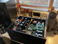
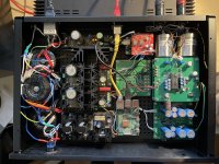
I finally found time to finish my dual D3 setup, RPi4b/moode audio/jlsounds/i2s sim V2/D3/30R rhopoint iv resistors/sowter 1465 trafo
Sounds very fine but I need a preamp with max 6…12db gain for my Pass J2 clone.
Sounds very fine but I need a preamp with max 6…12db gain for my Pass J2 clone.
Attachments

Hi ilgavro,Pcb is still available!?
Regards
Yes I still have some PCBs left, sorry for the late reply I have not had internet access for a while.
Great work!I finally found time to finish my dual D3 setup, RPi4b/moode audio/jlsounds/i2s sim V2/D3/30R rhopoint iv resistors/sowter 1465 trafo
Sounds very fine but I need a preamp with max 6…12db gain for my Pass J2 clone.
D
Deleted member 537459
No problem, i pay the invoice.Hi ilgavro,
Yes I still have some PCBs left, sorry for the late reply I have not had internet access for a while.
Hi all. I’m currently using a DDDAC with Ian’s FifoPi/ReClockPi as the I2S input.
@Supersurfer’s appraisal of Ryan’s boards compared to his DDDAC has piqued my interest, given that my DDDAC 4 boards, Sowter transformers etc) has seen off all other DAC’s I’ve tried in the last few years.
None of my amps have balanced connections but I am interested in a dual mono DAC. Does this mean I just need two DAC boards? Do I also need to order Ryans’s I2S board as well? I’ve not looked into the power supply or output yet….boards first then I can figure out the rest.
Also, if anyone finds a couple of 1541 chips behind their sofa please pm me ;-)
James
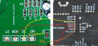
Connections look correct.
For TDA1541A and I2S input, DR is left open. If your chip is a non-A TDA1541, then DR (pin 4) needs to be connected to pin 2.
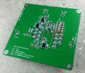
For I2S input, the I2S mode needs to be selected. On the D3 that is done on the underside of the board:
For TDA1541A and I2S input, DR is left open. If your chip is a non-A TDA1541, then DR (pin 4) needs to be connected to pin 2.
For I2S input, the I2S mode needs to be selected. On the D3 that is done on the underside of the board:
Attachments
- Home
- Group Buys
- DIY TDA1541A PCB "D3"