Transistor insulating pads
I'm a bit contused. I did some researching but can not come up with logical answer. I found opposing information.
I was using KERATHERM in my previous builds, and it worked fine but now I'm puzzled with thermal conductivity numbers for Alumina pads that have much better specs listed... Is there something I'm missing?? Perhaps thickness of alumina lowers conductivity
Here are two eg. on TO-247 insulation I have found on ebay_
KERATHERM Thermal Conductivity:1.4W/mK
Kerafol KERATHERMBRAUN70/50TO247 70/50 Thermal Transistor Pad TO247 1.4W/mK 2050000461064 | eBay
Alumina - Thermal Conductivity: ≥ 20.9 W/m.K
10 pcs Ceramic TO-247 Sheets 20x25mm T0.6mm Insulator Pads Transistor Heat Sink | eBay
Thermal conductivity data -20.9 W/mK- stated at the second link seems to be false, if you google for TO 247 pads with 20.9 W/mK no results come up except from some ebay listings, so I suppose these sellers are giving false data.
Please see the following table from an article by EUVL.
Attachments

Last edited:
Please see the following table:
Thank you! This table makes it all clear!!!
Shaan thank you very much for an easy and pleasant transaction, looking forward to build your amp.
Received the boards today, they look great, thank you very much Shaan.
 🙂
🙂I blew up my V4H!
As the title suggests, a few days ago I let the magic smoke out of my V4H 😱.
In my infinite wisdom, I was messing around with my turntable to identify a wee bit of background noise. During this time, I had my preamp cranked up full blast into the V4H. I unplugged my turntable from power, and then trying out a different power outlet, plugged it back in. Immediately after this, something popped within the V4H and a short period later, the mains circuit breaker in the amp tripped. My best bet is that somehow through plugging in the turntable I got some nasty transient / DC and then this got amplified by the phono pre and preamp and the V4H didn't handle it well.
Luckily, I think the speaker protection relays triggered, preventing any damage to my speakers. After a frustrated sigh (and other choice words), I opened up to identify the carnage...
I do not think any damage was done to the PSU, I still need to verify rail voltages, but everything looks undamaged. Surprisingly, the fuses I have on the DC rails did not blow, they are rated at 4A and I would have expected those to blow if the 5A mains breaker blew.
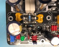
The main damage was to the V4H boards as seen in the attached photos. Specifically, it looks like the following are toast: right channel R23, R25, left channel R25. The right channel has what looks to be a lot of collateral damage (R17 / R27), but maybe is this is remnants from the exploded R25? Also, I can't tell what damage might have happened to VR1, not sure what physical damage would look like on a VR.
Before I start desoldering things and testing to see if they are still alive. What components do you expect will be destroyed from this incident? Should I just start with R23 / 25 on each channel and see if it works or given the state, are there other components I should definitely test / replace?
Sigh, I guess this is all part of DIY, but I miss my V4H, my hifi isn't the same without it!
Greg
As the title suggests, a few days ago I let the magic smoke out of my V4H 😱.
In my infinite wisdom, I was messing around with my turntable to identify a wee bit of background noise. During this time, I had my preamp cranked up full blast into the V4H. I unplugged my turntable from power, and then trying out a different power outlet, plugged it back in. Immediately after this, something popped within the V4H and a short period later, the mains circuit breaker in the amp tripped. My best bet is that somehow through plugging in the turntable I got some nasty transient / DC and then this got amplified by the phono pre and preamp and the V4H didn't handle it well.
Luckily, I think the speaker protection relays triggered, preventing any damage to my speakers. After a frustrated sigh (and other choice words), I opened up to identify the carnage...
I do not think any damage was done to the PSU, I still need to verify rail voltages, but everything looks undamaged. Surprisingly, the fuses I have on the DC rails did not blow, they are rated at 4A and I would have expected those to blow if the 5A mains breaker blew.
The main damage was to the V4H boards as seen in the attached photos. Specifically, it looks like the following are toast: right channel R23, R25, left channel R25. The right channel has what looks to be a lot of collateral damage (R17 / R27), but maybe is this is remnants from the exploded R25? Also, I can't tell what damage might have happened to VR1, not sure what physical damage would look like on a VR.
Before I start desoldering things and testing to see if they are still alive. What components do you expect will be destroyed from this incident? Should I just start with R23 / 25 on each channel and see if it works or given the state, are there other components I should definitely test / replace?
Sigh, I guess this is all part of DIY, but I miss my V4H, my hifi isn't the same without it!
Greg
Attachments

Oh man, that sucks Greg 🙁
Diya is like the old TV show 6Million Dollar Man,
“We can rebuild him”
Good luck re-building 🙂
Diya is like the old TV show 6Million Dollar Man,
“We can rebuild him”
Good luck re-building 🙂
“We can rebuild him“
Ha, I was telling my 5 year old what had happened and she said “oh no did you cry?!” I told her that’s the nice thing about building things yourself, if it breaks, you can fix it!
As the title suggests, a few days ago I let the magic smoke out of my V4H 😱 ...
Hi Greg.
The VAS was overloaded and the VAS emitter resistors burned. Q3 and Q4 could also be damaged, along with Q1 and Q2.
The resistors need only a couple hundred milliamps to burn so fuses won't blow to protect them, but if the mosfets get overloaded then the fuses will melt. So the mosfets should be fine.
I suggest you carefully replace all small signal transistors and VAS transistors in both channels, along with all burnt resistors. Also check continuity of diodes, insulation of the 2200uF feedback capacitors, resistance of the trimmers and status of the LEDs (if in doubt replace the LEDs).
All the bests.
p.s. during power on and off, most low level and line level circuitry puts out transients that have the potential to mess with the amp's input. i'm sorry this happened to you.
Last edited:
during power on and off, most low level and line level circuitry puts out transients that have the potential to mess with the amp's input. i'm sorry this happened to you.
Thanks shaan! No worries, I figure it's all part of the hobby, I've fortunately gotten pretty decent at desoldering though mistakes =) Taking time to dismantle the amp, I may actually be motivated to get the aluminum professionally finished and anodized and make some tweaks I may have otherwise been too complacent to fix.
Sorry for my ignorance of the V4H's (or any really) architecture. Are the VAS transistors Q9 and Q10? I should probably finish reading Cordell's book one of these days...VAS transistors
Ha, I was telling my 5 year old what had happened and she said “oh no did you cry?!” I told her that’s the nice thing about building things yourself, if it breaks, you can fix it!
How sweet of her 🙂
Great that you mentioned the goodness of DIY to her, and good to see that you're on the way to getting your amp fixed.
Update:
Hi everyone.
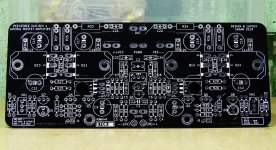
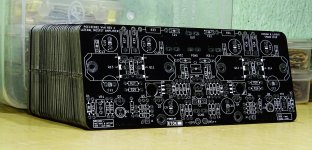
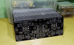
I printed a batch of 40 boards of V4H Rev1. Interested members won't have to wait for GB list until this batch lasts.
Leave a post or send me a PM if you need a pair or more.
Thanks
Hi everyone.
I printed a batch of 40 boards of V4H Rev1. Interested members won't have to wait for GB list until this batch lasts.
Leave a post or send me a PM if you need a pair or more.
Thanks
Attachments
Burned resistors in V4H amp
Hi Shaan,
Do you know what would cause R25 to get fried by powering down a preamp before the power amp? I've been testing a new Yarra preamp in my system, and when I turned it all off today it fried R25 in both channels. I'm just trying to diagnose what interaction between the pieces of equipment would cause this effect on the power amp. Any insight would be appreciated.
Hi.
It's two-folds.
First, preamps almost always have turn on/off transients of a high magnitude. Too fast a transient signal of high magnitude will cause the input of the amp to overload and send a high current signal to the VAS. The input is just responding to the signal it is presented.
Second, unlike typical CCS-fed VAS design, the symmetrical VAS has no inherent current limiting (one of the reasons why it has higher slew rate than an equivalent CCS-fed design). The high current signal from input overloads the VAS, causing either R25 or R26 or both to burn.
Now, if the amp is turned off before the preamp, then the rails of the amp has already started to decrease. And then if the pre is turned off and it sends a transient it will still try to overload the vas, but due to lack of continuous supply of current from the PSU the resistors won't burn.
In separate pre+power systems such as yours and many others (including my own), it is best to turn the amp off before anything else during power off, and also turn the amp on after everything else during power on.
I will suggest you also check Q3/Q4. Sometimes during an overloaded VAS the resistors tend take this pair with them.
Last edited:
Thanks for that explanation. I will pull the boards at some point and replace both the resistors and Q3 and Q4.
Update:
Hi everyone.
I printed a batch of 40 boards of V4H Rev1. Interested members won't have to wait for GB list until this batch lasts.
Leave a post or send me a PM if you need a pair or more.
Thanks
Hi Shaan, Just out of curiosity: do you know how many of your amps are out in the field?
Seems that a lot of people have build it.
Hi Shaan, Just out of curiosity: do you know how many of your amps are out in the field?
Seems that a lot of people have build it.
Hi Delange.
I have sold many PCBs but the number of reports of amplifiers built with it is far lower. Many buyers haven't yet started assembling and just kept it for a future project.
- Home
- Group Buys
- PeeCeeBee V4H GB