Juma uses V grade Jfets. To get the same level of Yfs, you would have to parallel two lesser BL grade. You can use just one if you pair if you like. I have considered the modular approach, but if this pre is as good as Juma suggest, dual mono is the ideal setup. The way the jfets are now, a single piece of thin copper can be run between all four and attached to the Jfets to allow for good thermal coupling. Put it in a sealed box and you will have little issue with thermal variation as the box will stablize the temperature after a time and not allow for any drafts to cause variation.
I received your PM, just trying to sort through previous committments first.
I received your PM, just trying to sort through previous committments first.
Juma uses V grade Jfets. To get the same level of Yfs, you would have to parallel two lesser BL grade. You can use just one if you pair if you like. I have considered the modular approach, but if this pre is as good as Juma suggest, dual mono is the ideal setup. The way the jfets are now, a single piece of thin copper can be run between all four and attached to the Jfets to allow for good thermal coupling. Put it in a sealed box and you will have little issue with thermal variation as the box will stablize the temperature after a time and not allow for any drafts to cause variation.
I received your PM, just trying to sort through previous committments first.
The copper bar sound like a good option, how would you secure it to the jfets though?
Theory for using SMD in this project is as follows. It allows for extremely tight spacing with short traces. Most of the SMD resistors used are 1% tolerance 25ppm Susume RG. The Susumu RL have been used in the 2512 positions as they are also 25ppm. IN the infamous resistor current noise paper, Susumu and Vishay TNPW SMD resistors matched the infamous vishay 102K in noise performance. The only things that beats them is the naked foil TX2575. A preamp seems like a likely place to shoot for uber low noise. I am not saying this is the perfect implementation by any means, but i think it will give you a good idea of the performance of the circuit. In a RIAA I built for my brother, I was unable to distinguish on any major level the difference between the SMD resistors used here and the TX2575 when used in any situtation where a resistor lies in the signal path. I was able to hear a distinguishable difference when compared t o through hole. I will send a pair to Juma to see if he agrees or not. He is a stickler, so I think he will be honest in his assessment.
and smd components - soldered or notBuzz,
I'm in for two boards.
Cheers,
Nic
")
@NicMac, soldered. I should have a price tomorrow.
@Ilquam,
I will post Juma's original comments.
http://www.diyaudio.com/forums/pass-labs/244106-lsk-pre-baf-2013-a-7.html#post3682031
@brianco,
Lets just hope it pans out like I hope and I dont look like a dodo
@Ilquam,
I will post Juma's original comments.
http://www.diyaudio.com/forums/pass-labs/244106-lsk-pre-baf-2013-a-7.html#post3682031
@brianco,
Lets just hope it pans out like I hope and I dont look like a dodo
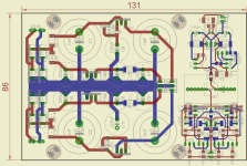
I have oriented that way for silly reason. I like the symmetry of the layout, equal length paths and such. You can see the sink on the inner regs. These same simks can be used on the outer fet regulators. THe outer regs will not be seeing a lot of heat ad are fairly tough.
I did realize that I did not put up a complete BOM. There are a few things missing.
I did realize that I did not put up a complete BOM. There are a few things missing.
FYI, I will try this pre with MKP1837 to start. It is an excellent value cap. If I were to recommend one to look at, it would be Audyn True Copper. Great thing about having a cap is the possibility to shape your sound a little.
@NicMac. While not a truly balanced implementation, Juma posted the same circuit used as a unity gain phase splitter. Might be a nice add on. The BF862 buffer could be jumpered or left in place, although it would seem unnecessary.
@NicMac. While not a truly balanced implementation, Juma posted the same circuit used as a unity gain phase splitter. Might be a nice add on. The BF862 buffer could be jumpered or left in place, although it would seem unnecessary.
I have oriented that way for silly reason. I like the symmetry of the layout, equal length paths and such. You can see the sink on the inner regs. These same simks can be used on the outer fet regulators. THe outer regs will not be seeing a lot of heat ad are fairly tough.
I did realize that I did not put up a complete BOM. There are a few things missing.
Gonna be hard to screw them to the case....cheaper than buying heatsinks.
True. I can switch, but I think the heatsinks are sufficient.
I would switch that lower transistor, it is easy to do with this layout.
- Status
- This old topic is closed. If you want to reopen this topic, contact a moderator using the "Report Post" button.
- Home
- Group Buys
- Juma's LSK Preamp - SMD version