I'm in when you are ready, no hurry for me.
Me too.
Anyone have a specific recommendation (digikey p/n) for the 0.1" headers?
BK
0.1 inch header 2-way Digikey PN: A26543-ND
0.1 inch header 3-way Digikey PN: A26545-ND
BOM Updated:
AKL-AMN-SXX BOM - View/Edit/Update
Last edited:
DQ,
If you're using the load to size a pre-regulator/transformer I would allow say 30mA at a rough guess.
The big load is the 4ch isolator. I looked at two different datasheets and came to the same answer:
NVE 715 isolator needs probably 15mA total.
Si 8440 Isol needs ~4mA per channel (4 channel for i2s and another few if you're doing DSDOE and mute isolation as well, if you don't need those signals then don't populate that isolator).
So this is roughly consistent between the two 4ch isolators, without looking at the datasheet for the 2ch isolators I'm just going to guess they'll be 6-10mA.
The potato FF doesn't specify a current draw, I assume that means its probably quite small but at 30mA you've got a bit of room to move there.
Back of the envelope and pretty rough but I think 30mA should be safe ... there is probably somewhere between a few uA to say 1mA lost in the ADP150 reg as well but not enough to make a big difference I'd guess.
Chris
Last edited:
DQ,
If you're using the load to size a pre-regulator/transformer I would allow say 30mA at a rough guess.
The big load is the 4ch isolator. I looked at two different datasheets and came to the same answer:
NVE 715 isolator needs probably 15mA total.
Si 8440 Isol needs ~4mA per channel (4 channel for i2s and another few if you're doing DSDOE and mute isolation as well, if you don't need those signals then don't populate that isolator).
So this is roughly consistent between the two 4ch isolators, without looking at the datasheet for the 2ch isolators I'm just going to guess they'll be 6-10mA.
The potato FF doesn't specify a current draw, I assume that means its probably quite small but at 30mA you've got a bit of room to move there.
Back of the envelope and pretty rough but I think 30mA should be safe ... there is probably somewhere between a few uA to say 1mA lost in the ADP150 reg as well but not enough to make a big difference I'd guess.
Chris
Excellent thank you, I am toying with a couple of approaches which I may post for advice.
thanks again
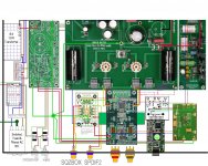
I'm thinking of using one of the TI Eval regulator boards I have laying around to feed the Isolator as per the attachment. The regulator will be fed from the Placid HD that should have plenty of mA left over because it is only feeding the BIII SE & an OTTO II.
The next bit is a bit OT well a lot OT really. In my first DAC the Arduino isn't connected to the BIII in anyway, so I felt fine using a good SMPS to run the Arduino. In the new DAC the BIII SE will be connected to the Arduino via the I2C input and the Star ground. I am still planning in using the SMPS but thought I might run it's output through one of the TI regulators to lower the noise before sending it to the Arduino.
Any thoughts on that approach?
Attachments
Last edited:
The I2C from Arduino must be isolated otherwise ground noise will affect the SQ a lot. With the isolator, you can use whatever PSU for Arduino.
This is correct, you really do want to isolate the i2c connection too.
The next bit is a bit OT well a lot OT really. In my first DAC the Arduino isn't connected to the BIII in anyway, so I felt fine using a good SMPS to run the Arduino. In the new DAC the BIII SE will be connected to the Arduino via the I2C input and the Star ground. I am still planning in using the SMPS but thought I might run it's output through one of the TI regulators to lower the noise before sending it to the Arduino.
Any thoughts on that approach?
If you chose to only build one of the re-clocker boards then you could probably adapt the second board as a general purpose isolator and not populate any of the re-clocking parts just the isol and its power supplies.
You should be able to achieve this with the Si8605 for example. Some of the io might be a bit messy because it is coming from the pin headers that Acko has provided for i2s but it should work quite nicely. If I get a chance later I'll work out exactly how this should work but at a glance the Si8605 pin out should be ok to drop into this board without too much hassle.
I'm thinking of using one of the TI Eval regulator boards I have laying around to feed the Isolator as per the attachment. The regulator will be fed from the Placid HD that should have plenty of mA left over because it is only feeding the BIII SE & an OTTO II.
Are you talking about using that instead of the onboard ADP150 or in addition to the ADP150? I think you might find it'd be overkill to use it as well as the ADP150 and unless you're careful with how you wire it up might not be an advantage to use it instead of the onboard LDO (if you run the wires a long way they may pick up more radiated noise than the better regulator might buy you, for example).
I thought I would just try the Potato section to see how it goes.If you chose to only build one of the re-clocker boards then you could probably adapt the second board as a general purpose isolator and not populate any of the re-clocking parts just the isol and its power supplies.
That would be GREATIf I get a chance later I'll work out exactly how this should work but at a glance the Si8605 pin out should be ok to drop into this board without too much hassle.

Are you talking about using that instead of the onboard ADP150 or in addition to the ADP150? I think you might find it'd be overkill to use it as well as the ADP150 and unless you're careful with how you wire it up might not be an advantage to use it instead of the onboard LDO (if you run the wires a long way they may pick up more radiated noise than the better regulator might buy you, for example).
As I was only going to use the Potato section it doesn't have a regulator on board so the regulator was necessary.
Thanks guys
PS: I'm still a little confused on exactly how the Dual board works & why you would want the two halves in one installation?
PS: I'm still a little confused on exactly how the Dual board works & why you would want the two halves in one installation?
The purpose of the dual board is just to give you an opportunity to trial both types of flip flops in circuits/pcbs that are optimised for each. A lot of people have trialed the flip flops in point to point/adapter pcbs and similar to just see how it goes. Unfortunately the faster switching speeds means that the signal integrity is compromised unless the circuit board is designed for HF content. Think of a square wave as a sum of a series of sine waves, the faster the rising edge the higher frequency sine wave is needed to approximate the square wave. This is exactly why people will say that the tr (rise time) of a signal is the deciding factor for whether a circuit is 'high speed' or not.
In short, some previous tests comparing flip flop types were hamstrung and not exactly fair. In other cases the board that the i2s signal is destined for is not designed to manage a fast signal that the potato FF will produce so it may in those cases be a better end result with the 'slower' FF.
In that case we're in businessThat would be GREAT
As I was only going to use the Potato section it doesn't have a regulator on board so the regulator was necessary.
Thanks guys
Actually, the Potato section did end up withe a regulator, Acko mentioned at one stage that he considered leaving it out, but U12 is a reg in the final BOM.
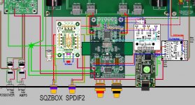
From the info that we have, I think that the Si8605 can be mounted on the S01 pcb and used to isolate the i2c between arduino/microcontroller and DAC. This would apply equally for people using say Acko's AKC12 or any other i2c/serial microcontroller.
From a look at the datasheet and the component layout what I think you'll need to do is:
- connect 3.3V and ground from the arduino to the amanero pin header area
- connect SDA and SCL to MCK and DATA positions on the amanero pin header area
- connect 5V or 3.3V from DAC to the similarly labeled headers on the isolator board (J1 or J3 respectively) 5V would probably be my preference, from the Placid HD that you're using as pre-reg for your DAC.
- connect SDA and SCL to i2c pin header from outputs labeled MCK and DATA (just be consistent with the connections you made on the input)
- only mount decoupling, FB filtering etc for the U1 and U7 positions. C1, C4, C13, C14, C15 and a few other positions look like the parts you'll be mounting. When the boards are ready Acko will provide subscribers with a schematic I believe so it will be more obvious then.
- the DAC side of the isolator will probably need pull up resistors. In this case a ~20k resistor between 3.3V regulated output and these output pins will be needed. Can probably try to squeeze a few through hole resistors in between 3.3V available on J3 and those two outputs
NB. Can anyone confirm if the BIIISE needs pull up resistors for its i2c input? I haven't used one or read up on it to confirm, more than likely this is the case though I believe.
There may even be a bi-directional isol that fits on the SOIC8 position instead of the SOIC16-W position that I'm suggesting for the Si8605. I haven't got a part number for that off the top of my head. In that case all that would change is to use DSDOE and MUTE instead of DATA and MCLK.
Clear as mud?
hochopeper
WOW thats excellent & so fast, thank you, I have saved the info in my spreadsheet for when the board & bits arrive, I started the spreadsheet as with my crappy memory I could never remember where bits of information where posted and could never find them again.
I am using a I2C Level convertor from I2C Level Converter & they say with there level converter "No need for external pullup resistors" I dont know if this answers your Pull Up resistor question thought. I assume I put the isolator on the BIII SE side of the level converter?
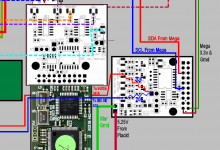
No worries mate I was actually looking at iancanada's general purpose isolator just last night so basically it is an adaptation of his circuit and the Si8605 datasheet to suit this PCB. But I did have the datasheets open and had been thinking about these things recently enough that I could do it mostly from memory!
Well, yes, I had forgotten the whole 5V Arduino thing, I had been looking at 3.3V arduino's last time I looked at them so hadn't caught on to the fact that your arduino had 5V TTL logic outputs. With the isolator you won't need that level convert at all. Connect 5V from arduino to the 3.3V on the amanero header positions on the S01 and just connect direct from the arduino to the S01 board and you'll be away. The isolator will do the level conversion for you as a secondary benefit of its isolation!
Instead of tracking things in a spreadsheet I use evernote and its browser plugin to clip forum posts and interesting web tutorials. I can tag them and search them all later, including searching text in images! Since all those notes are stored online I can also uses it to save articles to read over lunch at work The only thing it doesn't do particularly well is saving images attached to forum posts, but they can be downloaded and added to the same note by hand without too much hassle.
EDIT: I am pretty certain that you'll need the pull up resistors still, they may be internal to the level converter chip but they aren't in the isol chip so basically they're either on the BIIISE board or you need to use them on this board.
I was actually looking at iancanada's general purpose isolator just last night so basically it is an adaptation of his circuit and the Si8605 datasheet to suit this PCB. But I did have the datasheets open and had been thinking about these things recently enough that I could do it mostly from memory!Well, yes, I had forgotten the whole 5V Arduino thing, I had been looking at 3.3V arduino's last time I looked at them so hadn't caught on to the fact that your arduino had 5V TTL logic outputs. With the isolator you won't need that level convert at all. Connect 5V from arduino to the 3.3V on the amanero header positions on the S01 and just connect direct from the arduino to the S01 board and you'll be away. The isolator will do the level conversion for you as a secondary benefit of its isolation!
Instead of tracking things in a spreadsheet I use evernote and its browser plugin to clip forum posts and interesting web tutorials. I can tag them and search them all later, including searching text in images! Since all those notes are stored online I can also uses it to save articles to read over lunch at work
The only thing it doesn't do particularly well is saving images attached to forum posts, but they can be downloaded and added to the same note by hand without too much hassle.EDIT: I am pretty certain that you'll need the pull up resistors still, they may be internal to the level converter chip but they aren't in the isol chip so basically they're either on the BIIISE board or you need to use them on this board.
Last edited:
No worries mate
Well, yes, I had forgotten the whole 5V Arduino thing, I had been looking at 3.3V arduino's last time I looked at them so hadn't caught on to the fact that your arduino had 5V TTL logic outputs. With the isolator you won't need that level convert at all. Connect 5V from arduino to the 3.3V on the amanero header positions on the S01 and just connect direct from the arduino to the S01 board and you'll be away. The isolator will do the level conversion for you as a secondary benefit of its isolation!
Instead of tracking things in a spreadsheet I use evernote and its browser plugin to clip forum posts and interesting web tutorials. I can tag them and search them all later, including searching text in images! Since all those notes are stored online I can also uses it to save articles to read over lunch at work
EDIT: I am pretty certain that you'll need the pull up resistors still, they may be internal to the level converter chip but they aren't in the isol chip so basically they're either on the BIIISE board or you need to use them on this board.
Excellent, thank you again
David
Attachments
Last edited:
At a glance it looks like what I had in mind
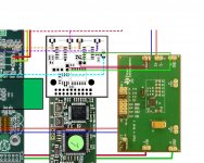
I think Acko has provided a through hole on the input to the flip flops and labled each so that you can use the board as just an isolator. The through hole just shows up as a small black dot beside C7 and FB1 and they are labelled with the signal name too.
I think Acko has provided a through hole on the input to the flip flops and labled each so that you can use the board as just an isolator. The through hole just shows up as a small black dot beside C7 and FB1 and they are labelled with the signal name too.
Another option would be Si8600 mounted on U2 position instead of IL711
Yes but whats the best option
thanks
Well Si8600 and Si8605 are just the 8pin and 16pin variant of the same chip, so from that perspective, no difference. The cost difference is ... less than $0.50.
The only difference that I can see is the wiring might be a touch neater and less susceptible to picking up radiated noise using the DSDOE and Mute output connections.
There is really nothing at all in it, just another option.
This option might be interesting for people who want to use the Amanero i2c connection for example by not populating the full 2x10pin header to the Amanero and take the signals from the other output pins on the amanero to the appropriate spots on the S01/S02 board. This would enable you to write a computer program for controlling your DAC and still enjoy isolation from computer noise and no need for arduino and extra PSUs. For a computer input only DAC that could be appealing I imagine and would mean it is all on the one PCB. The all on one PCB option isn't possible for you though because you need 5V on one side for the arduino.
Last edited:
- Status
- This old topic is closed. If you want to reopen this topic, contact a moderator using the "Report Post" button.
- Home
- Group Buys
- Amanero Isolator/Reclocker GB