I have not tried it myself but I have listened to it at Bert Doppenberg's place. The loudspeaker used was an AER MKI.
Mids and Highs were very good, very detailed and coherent. Best Highs I have ever heard from a fullrange driver, ribbon like resolution but with the guts and balls of a bigger dome tweeter. Tonal balance a little bit on the bright side but not near as bright as the typical Lowther sound. Bass output was limited in extension and power but basslines were very easy to follow. Stereo imaging was a bit on the small side (due to the lack of real low bass maybe) but very stable and precise. The sweetspot, while not huge, was much bigger than I expected. Except for the lowbass extension and capabilties it's a very nice system with no horn colouration or any noticable cabinet colouration.
They have all the goodies from a Lowther system (Dynamics, livelike sound and precise imaging) but you don't have to take ten aspirines after an hour of listening
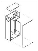
panel with 4 holes
It is simply there for to distub the waves, which are reflecting from the back of the enclosure. There were much reflection from the back of the enclosure radiating to my listening room through the thin cone of AER MK1s and I've decided to reduce the magnitude of the reflected waves by placing some obstacles on their way. On the other hand, I didn't want to divide the rear chamber into two parts, since I didn't know what may be the result of such a change therefore I have drilled holes to balance the pressure on the sides.
Ropie said:That's a big hybrid-type enclosure. What's the purpose of the panel with the four holes cut in it at the rear of the line?
It is simply there for to distub the waves, which are reflecting from the back of the enclosure. There were much reflection from the back of the enclosure radiating to my listening room through the thin cone of AER MK1s and I've decided to reduce the magnitude of the reflected waves by placing some obstacles on their way. On the other hand, I didn't want to divide the rear chamber into two parts, since I didn't know what may be the result of such a change therefore I have drilled holes to balance the pressure on the sides.
It is simply there for to distub the waves, which are reflecting from the back of the enclosure.
What is the damping material?
John
jlsem said:
What is the damping material?
It is one of the most important things about this TL. In theory you do not need any damping material, the enclosure handles the unwanted frequencies itself and yet you still can not sonically point your finger that you are listening to a TL design. But in real life things don't work out as they do on paper. When you need to fine tune the enclosure and when T/S parameters can not be anymore help, I prefer to use fiber which is 3 cm thick. The most important point about placing the damping material is not to fill the cross-section of the line completely.
Some Technical Questions for Onur
Onur,
My first post to this forum so please be kind if I am not following proper procedures for the posting of responses or the asking of questions.
I have been trying to decide on a design to follow for a new speaker system and the Singular is high on my list of designs and thank you for posting the design for the DIY community.
But I am wondering about the what I believe to be is a tuned reflex chamber that you employ behind the driver. What purpose does this chamber serve and how did you decide on volume and the tuned frequency if it is a tuned chamber?
Also, how did you decide on or calculate the cross-sectional of the transmission line?
Do you have a complete technical description that you care to share?
Lastly, can the designed be scaled for smaller Fostex drivers and if yes could you please share the methods to follow to scale the design?
Best regards,
Eric
Also, how did you decide on or calculate the cross-sectional of the transmission line?
Have you read this?
http://www.t-linespeakers.org/readme1st.html
interesting enclosure.
funny, a conversation the day before yesterday got me thinking and reading about broadband resonators.
a certain bobby steele, late of the Misfits and the Undead was picking up a nice old PSE gibson guitar amp with a field coil speaker that i rebuilt for him and we got to talking about his stage rig.
seems his dad gave him 2 Karlson cabinets he built long long ago. dad was big into DIY hifi and ham radio.
he loaded those cabs with EVM 15' speakers and has been using them ever since. says soundmen always rave about 'em...
he loved my little fostex backhorn that i'm tweaking...and we looked up this on the web:
http://home.planet.nl/~ulfman/
verrrryy interesstinggg
Some answers for Eric
Hi Eric,
Sorry for my late reply but because of my email change, I couldn't be informed about the postings on this forum. I hope I am not late for this.
Although many TL designers here do not agree with me on this, I believe that the reflected waves from the bends of the transmission line enclosure rise the distortion level. On the other hand, many people try to reduce the standing waves inside the transmission line enclosure by placing absorbing materials inside the line, causing the sensitivity to drop. To get rid of those two classical setbacks of the transmission line enclosure, I have built the rear chamber with a resonator tuned to the fundamental resonance frequency of the "complete enclosure" (not just the line) . The rear chamber gives the reflected waves room to expand rather then disturbing the cone. The notch generated with the helmhotlz resonator reduces the amplitude of the first standing wave frequency inside the enclosure to the flat level. By this way you get the cleanest sound from a TL enclosure with a higher sensitivity.
As for the cross-sectional area of the transmission line, it has been optimized for AER MK1 drivers in order to receive more low bass response.
Playing with the dimensions of this enclosure can make things worse while trying to make it suitable for another driver. You can make experiments with other drivers having similar diameters to see if there is some chance of finding the heavenly sound without getting lost in the dark and cold math forest") The enclosure is designed to work with a very small range of drivers (Low Q values) other then those driver units, the trial can be a good weekend enjoyment. By keeping the same principle, the enclosure can be re-designed for any driver unit for to take the best out of that unit.
The enclosure is designed to work with a very small range of drivers (Low Q values) other then those driver units, the trial can be a good weekend enjoyment. By keeping the same principle, the enclosure can be re-designed for any driver unit for to take the best out of that unit.
-Onur
Hi Eric,
Sorry for my late reply but because of my email change, I couldn't be informed about the postings on this forum. I hope I am not late for this.
Although many TL designers here do not agree with me on this, I believe that the reflected waves from the bends of the transmission line enclosure rise the distortion level. On the other hand, many people try to reduce the standing waves inside the transmission line enclosure by placing absorbing materials inside the line, causing the sensitivity to drop. To get rid of those two classical setbacks of the transmission line enclosure, I have built the rear chamber with a resonator tuned to the fundamental resonance frequency of the "complete enclosure" (not just the line) . The rear chamber gives the reflected waves room to expand rather then disturbing the cone. The notch generated with the helmhotlz resonator reduces the amplitude of the first standing wave frequency inside the enclosure to the flat level. By this way you get the cleanest sound from a TL enclosure with a higher sensitivity.
As for the cross-sectional area of the transmission line, it has been optimized for AER MK1 drivers in order to receive more low bass response.
Playing with the dimensions of this enclosure can make things worse while trying to make it suitable for another driver. You can make experiments with other drivers having similar diameters to see if there is some chance of finding the heavenly sound without getting lost in the dark and cold math forest
The enclosure is designed to work with a very small range of drivers (Low Q values) other then those driver units, the trial can be a good weekend enjoyment. By keeping the same principle, the enclosure can be re-designed for any driver unit for to take the best out of that unit.-Onur
Thank you, and I have 2 more questions
Onur,
Thank you for your reply to my questions. If you could please answer one more question then I will be able to go on and start some design.
Line length - Is the back chamber length added to the total line length when calculating the fundimental frequency of the line? I think it is since the cross-sectional area of the chamber matched the line cross-sectional area but am not sure.
Line Frequency - Could you please provide the basic line frequency? Knowing the frequency will help me fully understand the equations I use to model transmission lines.
The answer to the cross-sectional area of the line was as I expected - for the driver.
Best regards,
Eric
ScottG said:
reading my mind, you were. thanks for that.
noisenyc said:
reading my mind, you were. thanks for that.
in tune with the darkside, we are.. - anytime.
Line lenght is in no relation with the rear chamber dimensions, and it is only coincidence that they have the came cross-section area. They have some variables in common, they do effect each other but not in a way that you have mentioned. There are several ways of calculating the lenght of the line according to the driver unit. It can be very confusing since there are no documents about this subject. You can calculate the effective line length according to the correction method as given in Beraneks' book. You can take the center symetry line as Martin does and think that the shortest distance between the driver and the port passes through the symetry axis of the line. You may take the speaker unit or the start of the line as the referance starting point. You can use a rope and pull it between the start and the end of the line and regard its' lenght as the total line lenght (In this case you have to decide weather to take the center of the opening as the referance or one of its' corners). One of them will bring you to the same result with your simulation data, if the designer of the software has choosen the same method as you did Tricky ? Well, if you look at this as a hoby, it is nice, if make your living out of building TL enclosures, it must be hell !
Line frequency is simple to find. mutiply the total line length (no bends, no cross-section differences, just a simple pipe) of the pipe by 2 and divide the speed of sound with that number, it is your fundamental frequency. If there are bends, cross-section differences, rear chambers or resonators then you have to double click on your FEM softwares' icon since it will no longer be so simple to find. If you don't have any access to any of those software there are some other methods like, transfer matrix method (four pole), fem, and analytical. These are the ones you can perform by hand. In TMM (Munjal is the guy who has written the basics in his book) you simply mutiply the geometry matrices in between the source and the output, then according to the boundary conditions, which is p=0 at the open end, you find your resonance frequencies (the values which makes k=0, K=wave number), mostly used for finding transmission loss of the engine exhaust systems. In analytical method, you think that the input pressure and the output pressure are equal, also you think the same way with the volume velocities, and you generate your own analytical formulation for your specific line. There are minor differences between the methods like 1 or 1.5 Hz, so they all are dependable as far as audio is concerned.
-Onur
Tricky ? Well, if you look at this as a hoby, it is nice, if make your living out of building TL enclosures, it must be hell !Line frequency is simple to find. mutiply the total line length (no bends, no cross-section differences, just a simple pipe) of the pipe by 2 and divide the speed of sound with that number, it is your fundamental frequency. If there are bends, cross-section differences, rear chambers or resonators
then you have to double click on your FEM softwares' icon since it will no longer be so simple to find. If you don't have any access to any of those software there are some other methods like, transfer matrix method (four pole), fem, and analytical. These are the ones you can perform by hand. In TMM (Munjal is the guy who has written the basics in his book) you simply mutiply the geometry matrices in between the source and the output, then according to the boundary conditions, which is p=0 at the open end, you find your resonance frequencies (the values which makes k=0, K=wave number), mostly used for finding transmission loss of the engine exhaust systems. In analytical method, you think that the input pressure and the output pressure are equal, also you think the same way with the volume velocities, and you generate your own analytical formulation for your specific line. There are minor differences between the methods like 1 or 1.5 Hz, so they all are dependable as far as audio is concerned.-Onur
Dear Onur,
I have a wive . We have negotiated a maximum width of speaker cabinets in our living room of 22.5 cm (outer dimensions). Depth is not critical, heigth to a lesser extent. Now the question: can I make the cabinet smaller, without changeing the other dimensions?
Regards
Henk Koetzier
I have a wive
. We have negotiated a maximum width of speaker cabinets in our living room of 22.5 cm (outer dimensions). Depth is not critical, heigth to a lesser extent. Now the question: can I make the cabinet smaller, without changeing the other dimensions? Regards
Henk Koetzier
hkoetz said:
can I make the cabinet smaller, without changeing the other dimensions?
If you are talking about reducing the width to 22.5 cm externally then you are also reducing the cross-section area of the line, the volume of the Helmholtz resonator and the rear chamber volume. This will cause some loss in low end response of the enclosure. And the volume of the Helmholts resonator needs to be recalculated.
Which driver unit are you planning to use?
-Onur
- Status
- This old topic is closed. If you want to reopen this topic, contact a moderator using the "Report Post" button.
- Home
- Loudspeakers
- Full Range
- Has anyone tried the Singular Enclosure :) ?