A Karlson Compendium - Part One - "A New Approach in Loudspeaker Enclosures"
John Edward Karlson (Feb. 4 1910 - Jan. 18, 1973) was: an inventor, radar engineer, patent holder and co-founder, along with the late Wayne Green,
of a loudspeaker cabinet manufacturing company, Karlson Associates Imc., Brooklyn New York, and best known for his first commercial cabinet (now known
As “K15”.). K15’s prototype was built and tested in the summer of 1951, and introduced to the public at the fall 1952 HiFi show at The Hotel New Yorker, which
featured many of the luminaries of that golden age of Hi-Fi.
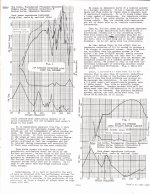
K15 was designed primarily for co-axial and full-range speakers of 15 inch size, and 12 inch speaker adapters were available. K15 has been ridiculed, and
touted one of the worst loudspeaker designs in history. It’s claims of flat response to the nether regions of bass are not true. What is true is that its capable of
a “musical” presentation when used with favorable drivers and also capable of agile bass at high peak amplitudes with very little cone movement. That is not apparent
from a simple graph. Over a certain region, horizontal polars can be improved vs a direct radiator. and distortion often than compromised mid bass and bass horns of equivalent
bulk.
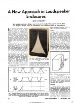
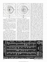
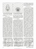
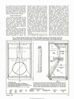
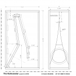
As Karlson’s first “Acoustic Transducer”s article states, the tilted baffle forms a wedge shaped chamber and the tapering in volume vs widening of the slot, less energy storage than with a box cavity. Also, the upward tilt of the baffle puts some of the treble lobes through a tapered diffraction slot.
The patent also states, the greater the baffle tilt, the worse
the effect upon transient response so for a given loudspeaker there may be an optimum cavity, baffle tilt, aperture taper, etc.
Also, the greater the baffle tilt, the more "reverb" effect.
K15, loaded with Electro-Voice’s 15TRX speaker, provided sound for a number of pavilion and exhibit including Disney at the 1964 through1965 World’s Fair.
To my knowledge K15 was produced basically without change other than minor port and shelf gap adjustments.
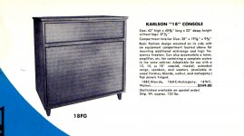
K15, btw, was not the largest regular production model. Karlson also had a K18 console with upper compartment for midrange and treble drivers/horns.
In the fall of 1954, a smaller model for 12 inch (and 8”, 10 with adapter boards) the “Karlson Twelve” was introduced. At that time it was known as the “Karlsonette” as there were only two models. This early “K12” had a reversible port panel, and three position moveable bar on the back panel to adjust the area of the rear shelf lowpass gap. A year later in 1955, the tiny Karlson Eight was introduced.
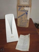
1956 brought the diminutive KR5 “Rocket” speaker which resembled a standard pyramid shaped metronome. KR5 became the inspiration for Karlson’s “Asymmetric Projector” speakers with supposed “clam” shaped dispersion pattern - - affectionately known now as “klams”. These projector speakers were manufactured both by Karlson, and under license by Karlson’s good friend, Jess Oliver.
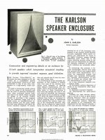
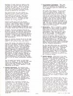
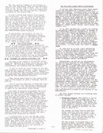
In this part is the 1952 Audio Engineering Magazine article
(Since I cannot go back and edit after 20 minutes to make a good table of contents, I’ll present this bit of history first - then plans in the next segment for the “heritage” lineup of Karlson Ultra-Fidelity models. - Then, hopefully links for the other Ks including GregB's Karlsonator series, and many ongoing threads by XRK971)
John Edward Karlson (Feb. 4 1910 - Jan. 18, 1973) was: an inventor, radar engineer, patent holder and co-founder, along with the late Wayne Green,
of a loudspeaker cabinet manufacturing company, Karlson Associates Imc., Brooklyn New York, and best known for his first commercial cabinet (now known
As “K15”.). K15’s prototype was built and tested in the summer of 1951, and introduced to the public at the fall 1952 HiFi show at The Hotel New Yorker, which
featured many of the luminaries of that golden age of Hi-Fi.
K15 was designed primarily for co-axial and full-range speakers of 15 inch size, and 12 inch speaker adapters were available. K15 has been ridiculed, and
touted one of the worst loudspeaker designs in history. It’s claims of flat response to the nether regions of bass are not true. What is true is that its capable of
a “musical” presentation when used with favorable drivers and also capable of agile bass at high peak amplitudes with very little cone movement. That is not apparent
from a simple graph. Over a certain region, horizontal polars can be improved vs a direct radiator. and distortion often than compromised mid bass and bass horns of equivalent
bulk.
As Karlson’s first “Acoustic Transducer”s article states, the tilted baffle forms a wedge shaped chamber and the tapering in volume vs widening of the slot, less energy storage than with a box cavity. Also, the upward tilt of the baffle puts some of the treble lobes through a tapered diffraction slot.
The patent also states, the greater the baffle tilt, the worse
the effect upon transient response so for a given loudspeaker there may be an optimum cavity, baffle tilt, aperture taper, etc.
Also, the greater the baffle tilt, the more "reverb" effect.
K15, loaded with Electro-Voice’s 15TRX speaker, provided sound for a number of pavilion and exhibit including Disney at the 1964 through1965 World’s Fair.
To my knowledge K15 was produced basically without change other than minor port and shelf gap adjustments.
K15, btw, was not the largest regular production model. Karlson also had a K18 console with upper compartment for midrange and treble drivers/horns.
In the fall of 1954, a smaller model for 12 inch (and 8”, 10 with adapter boards) the “Karlson Twelve” was introduced. At that time it was known as the “Karlsonette” as there were only two models. This early “K12” had a reversible port panel, and three position moveable bar on the back panel to adjust the area of the rear shelf lowpass gap. A year later in 1955, the tiny Karlson Eight was introduced.
1956 brought the diminutive KR5 “Rocket” speaker which resembled a standard pyramid shaped metronome. KR5 became the inspiration for Karlson’s “Asymmetric Projector” speakers with supposed “clam” shaped dispersion pattern - - affectionately known now as “klams”. These projector speakers were manufactured both by Karlson, and under license by Karlson’s good friend, Jess Oliver.
In this part is the 1952 Audio Engineering Magazine article
(Since I cannot go back and edit after 20 minutes to make a good table of contents, I’ll present this bit of history first - then plans in the next segment for the “heritage” lineup of Karlson Ultra-Fidelity models. - Then, hopefully links for the other Ks including GregB's Karlsonator series, and many ongoing threads by XRK971)
Attachments
The Ultra Fidelity Heritage Lineup - 1952 introduction of 15K aka "K15" w. plan
As previously discussed, the 15 inch driver Karlson enclosure made its debut in the fall of 1952 at the pretigous HiFi Fair hosted at The Hotel New Yorker.
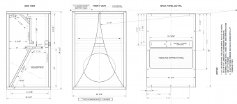
In the January 1954 issue of Radio and Television News, a second article was published with full dimensional details on how to build K15. The only change to K15 from that time on was narrowing of port width and shelf gaps, published in June of 1956.
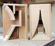
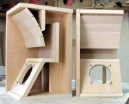
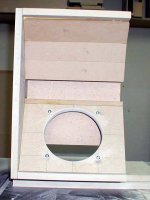
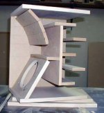
K15 should be braced to minimize cabinet "talk". Dowel struts from the front of the shelf to the wings works very well and likewise, a center strut from the rear shelf edge to the rear panel. Also, two on edge strips of plywood on the back panel works well to reduce flex as the lowpass shelf gap can put a lot of pressure on that panel.
It was another two years until the Karlson Twelve was introduced. In this 1954 article, John Karlson warns against scaling K15 by 0.8X, in practice
that works pretty well although the front shelf tends to deflect some highs from getting into the the upper part of the front chamber.
As previously discussed, the 15 inch driver Karlson enclosure made its debut in the fall of 1952 at the pretigous HiFi Fair hosted at The Hotel New Yorker.
In the January 1954 issue of Radio and Television News, a second article was published with full dimensional details on how to build K15. The only change to K15 from that time on was narrowing of port width and shelf gaps, published in June of 1956.
K15 should be braced to minimize cabinet "talk". Dowel struts from the front of the shelf to the wings works very well and likewise, a center strut from the rear shelf edge to the rear panel. Also, two on edge strips of plywood on the back panel works well to reduce flex as the lowpass shelf gap can put a lot of pressure on that panel.
It was another two years until the Karlson Twelve was introduced. In this 1954 article, John Karlson warns against scaling K15 by 0.8X, in practice
that works pretty well although the front shelf tends to deflect some highs from getting into the the upper part of the front chamber.
Attachments
-
 chngovrkit.jpg97.6 KB · Views: 721
 -
 KARLSON_RN6_1500x_1_1280x.jpg687.9 KB · Views: 476
 -
 KARLSON_RN5_1500x_1_1280x.jpg839.3 KB · Views: 395
 -
 KARLSON_RN4_1500x_1_1280x.jpg816 KB · Views: 393
 -
 KARLSON_RN3_1500x_1_1280x.jpg826.8 KB · Views: 585
 -
 KARLSON_RN2_1500x_1_1280x.jpg630.2 KB · Views: 756
 -
 KARLSON_RN_1_1500x_1_1280x.jpg630.7 KB · Views: 616
Ultra Fidelity in a much smaller package - The Karlson Twelve introduced in 1954
It was fall 1954, and introduction at the Hi Fi show of the little Karlson Twelve. At 3.3 cubic feet external bulk vs 7.3 for K15, this new "Karlsonette" presented a means for the public to try the Karlson concept with 12 inch fullrange and coaxial plus adapter boards were sold for 10 inch and 8 inch drivers.
This first K12 had a reversible port panel, and a 3 position movable bar adjacent to its rear lowpass shelf to allow some tweaking of impedance for the different drivers of its day.
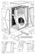
Sometime in 1956, (with details published in the July 1958 issue of Popular Mechanics, K12 while retaining the same external dimensions, underwent a few internal changes including a distributive 6 0 slit port panel which was canted 10 degrees forwards and a two board "shelf" arrangement which double to brace the back panel. Many speakers sold at that time had rather high qts and it was common among many makes to see semi resistive porting.
(Note, Karlson never went back to the front shelf after K15 in the regular lineup. It probably was employed with the 18 inch Karlson console.)
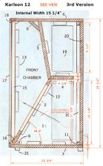
Sometime in the 1960's a "3rd K12" appeared, still the same size but in kit version, could be ordered with a blank port panel to custom port - or run with sealed back chamber. From the factory it had a 12 hole distributed port. (I've also seen factory K12 with 3 and 5 slit vents.)
It was fall 1954, and introduction at the Hi Fi show of the little Karlson Twelve. At 3.3 cubic feet external bulk vs 7.3 for K15, this new "Karlsonette" presented a means for the public to try the Karlson concept with 12 inch fullrange and coaxial plus adapter boards were sold for 10 inch and 8 inch drivers.
This first K12 had a reversible port panel, and a 3 position movable bar adjacent to its rear lowpass shelf to allow some tweaking of impedance for the different drivers of its day.
Sometime in 1956, (with details published in the July 1958 issue of Popular Mechanics, K12 while retaining the same external dimensions, underwent a few internal changes including a distributive 6 0 slit port panel which was canted 10 degrees forwards and a two board "shelf" arrangement which double to brace the back panel. Many speakers sold at that time had rather high qts and it was common among many makes to see semi resistive porting.
(Note, Karlson never went back to the front shelf after K15 in the regular lineup. It probably was employed with the 18 inch Karlson console.)
Sometime in the 1960's a "3rd K12" appeared, still the same size but in kit version, could be ordered with a blank port panel to custom port - or run with sealed back chamber. From the factory it had a 12 hole distributed port. (I've also seen factory K12 with 3 and 5 slit vents.)
Attachments
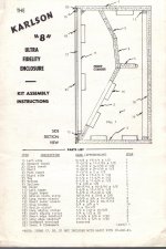
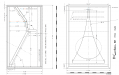
1955 - The introduction of the "Karlson 8"
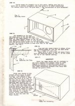
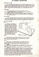
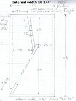
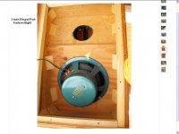
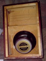
With decorative trim, the Karlson 8 aka "K8" was only 17.25" high, by 10.75" wide by 10" deep, nominal small signal tuning around 95Hz. Of course with some drivers it would work better with the distributive vent slit sealed or damped for ~ "aperiodic" results.
The first K8 had a 10 degree slant reflector port board. The 1960's model a two panel reflector. One version of the earlier model has been seen with a 3 inch round hole vent.
Attachments
-
 K8ASSEMBLYPAGE4.JPG348.4 KB · Views: 357
 -
 K8ASSEMBLYPAGE3.JPG277 KB · Views: 347
 -
 K8ASSEMBLYPAGE2.JPG352.9 KB · Views: 361
 -
 K8ASSEMBLYPAGE1.JPG266.1 KB · Views: 398
 -
 1960S KARLSON K8 PLAN.png340.8 KB · Views: 613
 -
 k8 1955 WEB.JPG529.8 KB · Views: 397
 -
 K8 1955 FRONT.jpg703.8 KB · Views: 362
 -
 ROUND PORT K8.jpg65.3 KB · Views: 343
 -
 BOFU20Z1955K8.GIF67.7 KB · Views: 331
 -
 1955K8REARVIEWZH4.JPG128.3 KB · Views: 478
K8 - continued
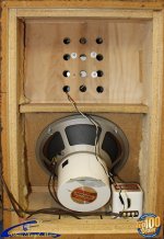
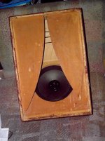
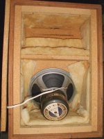
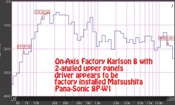
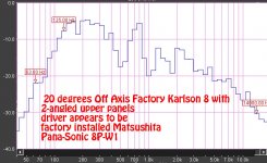
one very popular full range speaker of the Karlson 8's time was the Pana-Sonic 8P-W1 - unfortunately my sample was pretty much dead on arrival from Ebay.
Note the damping placement. This K8 came with fiberglass, Kim-sul paper insulation was common too in those days and nice to work with vs fiberglass.
For those not familiar here's a nice picture of that Pana-Sonic full range speaker with its ball diffusor
http://glowinthedarkaudio.com/national-panasonic-8P-W1/national-panasonic-8P-W1-2.jpg
Attachments
Last edited:

Reached limit of uploads
The little Karlson KR5 tabletop speaker was covered more extensively in the following thread.
Its interesting that Cetec-Gauss developed a K18 from scratch when Karlson had one listed in this brochure, which suggests the drawing was not passed to them when buying a license from Karlson's widow.
I've tried to upload five different times over the last 35 minutes but seem to have reached a limit and can't upload anymore.
I don't have $20 to upgrade my account - outgo is much more than income
I can use IMGUR to finish the blog
hope the moderator allows me to delete this message and its title.
The KR5 Rocket Plus A Nice 1960's Karlson brochure showing the "K18" console
The little Rocket (1957) and Karlson's K18 console sometime in the 1960's appear to be the last of the Ultra -Fidelity entries before the entry of the X15 system (announced fall of 1965)
KR5 was covered more extensively in the following thread: NASA consultant John Karlson, his little KR5 "Rocket" and Rise of the Klam projectors
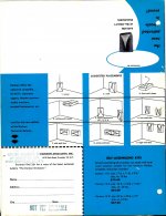
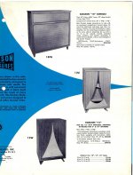
This Karlson brochure shows the 18 inch cabinet which laid the slot on its side and featured an upper chamber for midrange and treble drivers /and or horns.
The little Rocket (1957) and Karlson's K18 console sometime in the 1960's appear to be the last of the Ultra -Fidelity entries before the entry of the X15 system (announced fall of 1965)
KR5 was covered more extensively in the following thread: NASA consultant John Karlson, his little KR5 "Rocket" and Rise of the Klam projectors
This Karlson brochure shows the 18 inch cabinet which laid the slot on its side and featured an upper chamber for midrange and treble drivers /and or horns.
Attachments
Fast forwarding to the current generation of Karlsonator and other K-variant
Some years ago, long time Karlson participant, luthier, and musician, GregB came up with a useful hybrid whose name is "Karlsonator". For a given size they are tuned quite a bit lower than the heritage Karlson speakers.
Greg drafted plans for 3 sizes originally: 12 inch driver, 8 inch driver, and 6 inch driver. Those are included here plus a plan for Mark Audio's CHR70 driver,
The prolific and gifted XRK971 created a whole new crop of this type with his scalable Akabak script.
Also, XRK971 came up with new alignments based on bandpass simulation named "XKi", and a Z-baffle KaZba arrangement for subwoofers,
THESE are XRK971's Current K-related threads:
Mini Karlsonator (0.53X) with Dual TC9FD's
Mini Karlsonator (0.53X) with Dual TC9FD's
The XKi:
XKi - X's ab initio Karlson 6th Order Bandpass
XKi - X's ab initio Karlson 6th Order Bandpass
The KaZBa:
Rockin' the KaZba Dipole (K aperture Z-baffle Dipole)
Rockin' the KaZba Dipole (K aperture Z-baffle Dipole)
A Speaker that Kicks Butt in Large Spaces
A Speaker that Kicks Butt in Large Spaces
X looks at Karlson's slotted pipe tweeter
Karlson's slotted pipe tweeter
Attachments
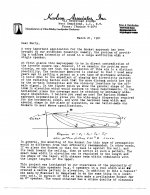
Also of note - Karlson Oliver Klams and Moray James' K Quarter Wave T-Line
the klam projector is pretty well covered in the KR5 Rocket thread as KR5 was the genesis for the klam speakers as illustrated in this 1961 letter from John Karlson to the late Martin Carl Poppe. Back at my home pc, there may still a plan for a 12 foot long Karlson speaker.
Long time K-supporter with critical "ear" made a series of K-type with 1/4 wave rear tunnel loading vs the reflex type in tradition - "heritage" Karlson cabinets.
Karlson spoke of the time when computers could aid design of his loudspeakers - I think we are in it "now" and more will be learned.
Attachments
The X15 two way system including the first tweeter - a mini klam w. 3" cone driver
Covered in this thread:
Karlson's "X15" A New Frontier in the Perfect Size
Covered in this thread:
Karlson's "X15" A New Frontier in the Perfect Size
Later X15 cabinets employed the "K-tube" tweeter
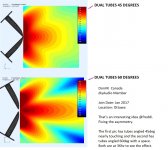
The first X15 cabinets had a wood mini klam driven by a 3 inch cone speaker. Subsequent X15 used a slotted pipe driven by a one inch format compression driver.
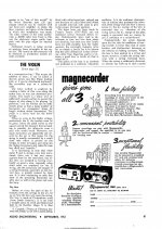
The most famous K-tube is the product from Walter Alan Zintz's "Transylvania Power Company" called "THE TUBE"
These tubes produce a symmetrical horizontal pattern and asymmetric vertical pattern.
(Wolf von Langa bragged about the tube too.)
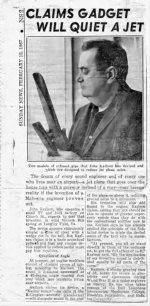
Karlson had an open end waveguide patent, and a jet nozzle /mufller patent.
Lately through the work of Moray James with paper tubes and Pelanj with printed tubes that simulations by DonVK show the double slotted tube is also of value for hi-fi.
a few pictures
The first X15 cabinets had a wood mini klam driven by a 3 inch cone speaker. Subsequent X15 used a slotted pipe driven by a one inch format compression driver.
The most famous K-tube is the product from Walter Alan Zintz's "Transylvania Power Company" called "THE TUBE"
These tubes produce a symmetrical horizontal pattern and asymmetric vertical pattern.
(Wolf von Langa bragged about the tube too.)
Karlson had an open end waveguide patent, and a jet nozzle /mufller patent.
Lately through the work of Moray James with paper tubes and Pelanj with printed tubes that simulations by DonVK show the double slotted tube is also of value for hi-fi.
a few pictures
Attachments
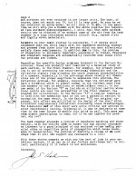
A Few Notes from the late Martin Carl Poppe (who wrote "The K-Coupler" paper"
Marty gave me permission to publish these on the late Gregg Baker's Karlson speaker forum.
a few old notes from Poppe
« on: May 08, 2008, 11:20:05 AM »
thought I'd post a few of these for "awhile" in case anyone is interested
**************
John initially thought in terms of what he called omni-resonance across the whole audio spectrum purely as a function of the tapered opening, an idea that I never fully accepted. My thesis studied the front-loading aspect of the exponentially loaded acoustical wave-guide, e.g., the Karlson Rocket. This led me to two thoughts.
1) The top of the rocket should not come to a point, but remain as a smaller opening. He build, but I do not think he sold, an enclosure that looked like the Rocket, but had a 5x7 inch (or what ever the standard size near that was/is) oval speaker in a “pipe with a roughly 6/8 inch cross section that tapered in from the front to about 8x2 inches. The taper was on the front that was maybe 10 to 12 inches and opened to the full width at the top. The back of the speaker was a small chamber, with the 6x8 cross-section and say 4” deep, perhaps filled with damping material (fiber glass?).
2) The standard Karson enclosure is really a fairly complex acoustical structure. The rear loading plus the front chamber I think of as a multi-pole low-pass filter, designed to match the speaker impedance over a fairly wide bandwidth at low frequencies, while the front loaded cavity with its exponential taped kept the front chamber from resonating at mid-range frequencies, in effect, got it out of the way acoustically. At frequencies where the tweeter kicked in and where several wave lengths of sound “fit” inside the enclosure, the front was designed to let the sound out as through a slot radiator, giving the enclosure a good high frequency dispersion pattern. I recall John manually ray tracing from the tweeter to the reflecting walls of the front cavity (many coats of lacquer) forming part of an elliptical curve. Sound directed toward the top of the front chamber reflected off the inner front chamber, top, back and out the middle / bottom. Draw a dimensionally correct X-15 side view and trace rays from the tweeter as they bounce around inside the front chamber. Note that mounting a tweeter horizontally (standard procedure for the early enclosures) sends more energy up and against the front wall, as opposed to the sides of the front chamber.
Regarding a question you asked a while ago, it was standard procedure to lay the enclosures on their back and point them towards a wall to make a “wall of sound.” I recall at least one installation (a movie star I think) where the speakers were installed in the ceiling pointing downward towards at flat wall. This installation pre-dated Dr. Bose’s use of the idea.
That’s it for now; I have billable hours to chase.
Marty
*************
Freddy,
Hummm, my recollection of the X-15 is that it had a good bass response.
What it did improve on was the transparency (lack of resonances??) in the
mid-range.
Regarding pressure on the speaker. If the low pass filter formed by the
chambers and chokes (the shelf and the opening to the front) in the back of
the speaker enclosure and the top of the front chamber is a multi-pole
filter, then it is possible for the sound pressure from the back of the
speaker (which is 180 degrees out of phase with the front) to be phase
shifted over a reasonable (low) frequency range so that it applies an
in-phase pressure wave to the front of the speaker (i.e., a low -pass filter
with constant phase shift). So, my guess is that it is not only the
pressure built up in the front of the speaker by the front cavity, but phase
shifted pressure from the rear also "pressing"on the speaker. This is my low
frequency lumped model of the enclosure, vs. John's omni-resonant everywhere
statement (An all-pass filter with constant phase shift ?).
At low frequencies I suspect that the exponential (or other opening shape for that
matter) is not the primary active element. By the way, one would also want
the low pass filter to block most of the energy from the rear once the
speaker diameter gets to be in the wavelength range where the speaker is
well coupled to the air. However, having put the chamber in front, now it remains to get it out of
the way at the mid-range frequencies where the sound wavelengths are on the
order of the cabinet dimensions, i.e., we are transitioning from a lumped
resonator model to a wave structure ( 400 Hz has a 1/2 wave length of about
one-foot) Here is where I believe the exponential pipe / K-Coupler effect
comes into play, leaking out the mid and hi frequency range energy without
creating a bunch of resonances. Further, as the wavelength move up in
frequency, the opening, especially the narrower top, starts to act as a
slotted radiator, increasing the high frequency dispersion Patten.
So, the enclosure is not simply a folded long pipe with an exponential slot.
The K-Couple is one element, and my guess is that it is not the fundamental
element at bass frequencies.
Again, these are only thoughts, based somewhat on what I remember John
talking about and my own insight. I have not simulated any of this and I am
open to other interpretations. Perhaps it is the simplicity of saying it
all works as on omni-resonant pipe (a term I have never really accepted,
vs.. a wide band impedance matching element) that put the experts off, and
stops them from looking further.
Marty
Martin Carl Poppe
CAMBRIDGE ENGINEERING, Inc.
**************
Freddy,
Sound power is velocity times pressure. You can get the same power with High pressure and low velocity as with low pressure and high velocity. If the speaker is impedance matched at low frequencies, it works against a higher pressure at a lower velocity (at low frequencies -i.e., wave length compared to speaker diameter- a speaker mounted in a flat wall slips freely through the air) . At a fixed frequency, higher velocity is obtained by moving the cone further in and out. A row boat is a good example. Try rowing with the oars out of the water. If you wave them fast enough you will move the boat along with your breeze. Now put them in the water and a low velocity higher pressure pull will move you along quite efficiently. A horn structure is an impedance matching device that loads the speaker with the right amount of back pressure for the impedance of the speaker.
John always touted the high efficiency of his enclosures. We could make more sound with a 5 watt amplifier than an AR-2 could with 20 or 30. Of course, the maximum power transfer occurs when the impedance of the source (the speaker piston) matches the impedance of the air in the structure it radiates into -- in this case the front chamber of the enclosure.
When I was a teenager the recording of the 1812 overture with real a real cannon was a big HiFi deal. An AR bass reflex speaker would jump about 1" on the cannon blast, while the Karlson (E-V triax 15" in the original 15 enclosure) moved about 1/8 inch. As I have said before, I've often wondered about the Doppler spread of mid-range signals radiating from a speaker moving +/- 1" on a low note.
Marty
Martin Carl Poppe
CAMBRIDGE ENGINEERING, Inc.
************
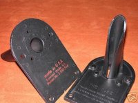
As I understood at the time, Robert Moses was growing hard of hearing, but did not want to wear a hearing aid. His fix was to have a clandestine sound reinforcement system installed in his office (spiffy place all Cherry paneling -- the real stuff it appeared -- , private bath, back door for leaving while leaving the press in the lobby -- hidden in an ugly Quonset hut on the old Worlds Fair grounds in Flushing NY). The problem was feedback. Several others tried to install solutions, frequency shift, etc. I do not know how John got the job, but his proposal was to place directional microphones on the desk facing the people seated across from Moses and directional speakers in the ceiling facing Moses. There were two Microphones and two speakers. The microphone was a Rocket speaker looking design, except it was quite a but skinner and shorter. I remember something maybe 2" x 2" inches at the base and 10 inches tall. I believe there was a microphone element inside, but he might have used a small loudspeaker (remember the telephone type voice band was all that was of interest, not High Fidelity). The Speakers were the Karlson ceiling speakers placed in the ceiling, over the microphones. The amplifier was in a closet - I believe it had a remote volume control and was there from a previous attempt by someone else, maybe even Bell Labs. John's system seemed to work in that you could detect a good degree of reinforcement without feedback. Whether Moses was finally helped by the system or not I do not know. I remember John being proud that the Rocket microphones on the desk could pass as an abstraction of the World Trade Center. I went along with John for the final installation.
From:
http://www.gothamist.com/archives/2005/05/18/trumps_wtc_solution_if_its_broke_build_it_again.php
The World Trade Center barely had any tenants when it was first put up and sat vacant for years. It was always a vanity project. And it was built in direct response to the fact that Rober Moses was unable to completely wipe out all of lower Manhattan. Robert Moses then decided that if he could not bulldoze the city to suit his vision, he'll just build a huge monument to the square-footage he wanted out of his original vision.
_________________________________________
Got to run
Marty
*************
Freddy (copy to Carl)
I do not have a mathematical way, except to exponentially decay the cross
section to say 1/4 the initial depth, vs. linear to zero.
I recall an experimental rocket type enclosure for a 6x9 inch speaker that John built.
6x9 were a good choice in "those days" as they were becoming in demand as car radio speakers,
especially for the then new concept of providing front and rear deck speakers.
The 6x9 fit well into the allotted size and they had to take a bit of power.
The basic dimensions as I recall were a cross section to fit a 6x9 inch speaker,
straight sides, a back chamber maybe 3 to 4 inches deep, a front chamber perhaps 12 inches high.
The slot started at say 1/2 inch, and opened to the full width of the 9 inch dimension,
and the top was fully open. Again, the sides were parallel, and perhaps the back
was 3 inches higher than the front, i.e.sloping sides.
I have attached a sketch and a repeat of the sketch of the stereo enclosure
I build in the MIT hobby shop in 1961.
I do not know what happened to the 6x9 enclosure, or where it was used.
Did I ever tell you of the sound reinforcement system that we put into Robert Moses'
office at the old world fair grounds?
Marty
Martin Carl Poppe
CAMBRIDGE ENGINEERING, Inc.
***********
Freddy,
The only earthquake story I know related to shaking a hotel during a demonstration / HiFi show. Note what I recall was pre-stereo. I quite sure it was the original 15 inch speaker enclosure. I'm not sure of the driving force, it might have been a sine wave, but an organ pedal note or mechanical feedback may also have done the trick . I know that feedback was always a problem with 33 1/3 rpm recordings if the turntable was anywhere near the speaker. (Always keep in mind that shaking buildings and the like is much easier than making music.)
John worked hard to eliminate resonance in the bass and mid-range. One way he would chase mid-range stuff was to listen for extended periods and see what started to drive him nuts. If after a long time one note was ringing in his head, he knew he had to change something. My memory of this exercise goes back mainly to the 4" speaker "rocket" enclosure. Regarding the port changes, my guess is that they had a lot to due with smoothing out the bass. I recall one of the earlier 12 inch speaker enclosures being referred to as the "bassey 12." Several were made and then sold at discount. The main changes to all the designs was in the port area and a bit with the curve of the opening. I recall several of the prototype speaker having either adjustable plate screwed in plates to close up the internal poets, holes drilled in to open things up, and larger pieces screwed over the whole area with the lasted port cut in them. I remember seeing a dusty model with a more open curve, but during my time I do not remember curve adjustments being made.
I have copied Shelby, as he seems to share your interest.
Martin Carl Poppe
CAMBRIDGE ENGINEERING, Inc.
*************
Freddy,
The ray tracing just assumed that the sound reflected off the the lacquer surface the way light reflects off a mirror, the angle of incidence equaling the angle of reflection. See attached drawing / PDF file.
I think John was happy with the X-15, but time and the cost of building prototypes always conflicted with the need to ship something. Getting good / the best speakers was always a problem in the later, e.g., the "X-15" days. Early on when it was common to purchase separate enclosures and speakers, the speaker manufacturers would give John free speakers to push their product. Later on, it was necessary to find OEM speakers already in manufacture, or have one custom designed and produced at a cost that John could not even start to think about. The X-15 speaker was designed for and used in an electric organ.
You asked about John directing church choirs. As I recall he did, but I am not sure how intense an effort this was. Anne played the piano and organ, and made some money playing for various churches. What surprise me at his funeral was the large showing of people from the Battery(?) Mission in New York City. It was there that he and Anne gave a lot of time and, I suspect, what money they could spare trying to help others. I remember purchasing and delivering to some gas station in Brooklyn, NYC a fuel pump for his Nash Rambler. His car had died while he was returning from Manhattan, and, not being able to afford to purchase the pump locally, he needed a delivery. I believe he installed it himself on the "Sidewalks of New York!"
You may post my ramblings if you wish. In an email I offered Job Ulfman a copy of one of the original Karlson data sheets, but never received a response. Is he still interested in Karlson, etc? Is there a better address for him than the one on the web site?
Marty
Martin Carl Poppe
CAMBRIDGE ENGINEERING, Inc.
*************
Marty gave me permission to publish these on the late Gregg Baker's Karlson speaker forum.
a few old notes from Poppe
« on: May 08, 2008, 11:20:05 AM »
thought I'd post a few of these for "awhile" in case anyone is interested
**************
John initially thought in terms of what he called omni-resonance across the whole audio spectrum purely as a function of the tapered opening, an idea that I never fully accepted. My thesis studied the front-loading aspect of the exponentially loaded acoustical wave-guide, e.g., the Karlson Rocket. This led me to two thoughts.
1) The top of the rocket should not come to a point, but remain as a smaller opening. He build, but I do not think he sold, an enclosure that looked like the Rocket, but had a 5x7 inch (or what ever the standard size near that was/is) oval speaker in a “pipe with a roughly 6/8 inch cross section that tapered in from the front to about 8x2 inches. The taper was on the front that was maybe 10 to 12 inches and opened to the full width at the top. The back of the speaker was a small chamber, with the 6x8 cross-section and say 4” deep, perhaps filled with damping material (fiber glass?).
2) The standard Karson enclosure is really a fairly complex acoustical structure. The rear loading plus the front chamber I think of as a multi-pole low-pass filter, designed to match the speaker impedance over a fairly wide bandwidth at low frequencies, while the front loaded cavity with its exponential taped kept the front chamber from resonating at mid-range frequencies, in effect, got it out of the way acoustically. At frequencies where the tweeter kicked in and where several wave lengths of sound “fit” inside the enclosure, the front was designed to let the sound out as through a slot radiator, giving the enclosure a good high frequency dispersion pattern. I recall John manually ray tracing from the tweeter to the reflecting walls of the front cavity (many coats of lacquer) forming part of an elliptical curve. Sound directed toward the top of the front chamber reflected off the inner front chamber, top, back and out the middle / bottom. Draw a dimensionally correct X-15 side view and trace rays from the tweeter as they bounce around inside the front chamber. Note that mounting a tweeter horizontally (standard procedure for the early enclosures) sends more energy up and against the front wall, as opposed to the sides of the front chamber.
Regarding a question you asked a while ago, it was standard procedure to lay the enclosures on their back and point them towards a wall to make a “wall of sound.” I recall at least one installation (a movie star I think) where the speakers were installed in the ceiling pointing downward towards at flat wall. This installation pre-dated Dr. Bose’s use of the idea.
That’s it for now; I have billable hours to chase.
Marty
*************
Freddy,
Hummm, my recollection of the X-15 is that it had a good bass response.
What it did improve on was the transparency (lack of resonances??) in the
mid-range.
Regarding pressure on the speaker. If the low pass filter formed by the
chambers and chokes (the shelf and the opening to the front) in the back of
the speaker enclosure and the top of the front chamber is a multi-pole
filter, then it is possible for the sound pressure from the back of the
speaker (which is 180 degrees out of phase with the front) to be phase
shifted over a reasonable (low) frequency range so that it applies an
in-phase pressure wave to the front of the speaker (i.e., a low -pass filter
with constant phase shift). So, my guess is that it is not only the
pressure built up in the front of the speaker by the front cavity, but phase
shifted pressure from the rear also "pressing"on the speaker. This is my low
frequency lumped model of the enclosure, vs. John's omni-resonant everywhere
statement (An all-pass filter with constant phase shift ?).
At low frequencies I suspect that the exponential (or other opening shape for that
matter) is not the primary active element. By the way, one would also want
the low pass filter to block most of the energy from the rear once the
speaker diameter gets to be in the wavelength range where the speaker is
well coupled to the air. However, having put the chamber in front, now it remains to get it out of
the way at the mid-range frequencies where the sound wavelengths are on the
order of the cabinet dimensions, i.e., we are transitioning from a lumped
resonator model to a wave structure ( 400 Hz has a 1/2 wave length of about
one-foot) Here is where I believe the exponential pipe / K-Coupler effect
comes into play, leaking out the mid and hi frequency range energy without
creating a bunch of resonances. Further, as the wavelength move up in
frequency, the opening, especially the narrower top, starts to act as a
slotted radiator, increasing the high frequency dispersion Patten.
So, the enclosure is not simply a folded long pipe with an exponential slot.
The K-Couple is one element, and my guess is that it is not the fundamental
element at bass frequencies.
Again, these are only thoughts, based somewhat on what I remember John
talking about and my own insight. I have not simulated any of this and I am
open to other interpretations. Perhaps it is the simplicity of saying it
all works as on omni-resonant pipe (a term I have never really accepted,
vs.. a wide band impedance matching element) that put the experts off, and
stops them from looking further.
Marty
Martin Carl Poppe
CAMBRIDGE ENGINEERING, Inc.
**************
Freddy,
Sound power is velocity times pressure. You can get the same power with High pressure and low velocity as with low pressure and high velocity. If the speaker is impedance matched at low frequencies, it works against a higher pressure at a lower velocity (at low frequencies -i.e., wave length compared to speaker diameter- a speaker mounted in a flat wall slips freely through the air) . At a fixed frequency, higher velocity is obtained by moving the cone further in and out. A row boat is a good example. Try rowing with the oars out of the water. If you wave them fast enough you will move the boat along with your breeze. Now put them in the water and a low velocity higher pressure pull will move you along quite efficiently. A horn structure is an impedance matching device that loads the speaker with the right amount of back pressure for the impedance of the speaker.
John always touted the high efficiency of his enclosures. We could make more sound with a 5 watt amplifier than an AR-2 could with 20 or 30. Of course, the maximum power transfer occurs when the impedance of the source (the speaker piston) matches the impedance of the air in the structure it radiates into -- in this case the front chamber of the enclosure.
When I was a teenager the recording of the 1812 overture with real a real cannon was a big HiFi deal. An AR bass reflex speaker would jump about 1" on the cannon blast, while the Karlson (E-V triax 15" in the original 15 enclosure) moved about 1/8 inch. As I have said before, I've often wondered about the Doppler spread of mid-range signals radiating from a speaker moving +/- 1" on a low note.
Marty
Martin Carl Poppe
CAMBRIDGE ENGINEERING, Inc.
************
As I understood at the time, Robert Moses was growing hard of hearing, but did not want to wear a hearing aid. His fix was to have a clandestine sound reinforcement system installed in his office (spiffy place all Cherry paneling -- the real stuff it appeared -- , private bath, back door for leaving while leaving the press in the lobby -- hidden in an ugly Quonset hut on the old Worlds Fair grounds in Flushing NY). The problem was feedback. Several others tried to install solutions, frequency shift, etc. I do not know how John got the job, but his proposal was to place directional microphones on the desk facing the people seated across from Moses and directional speakers in the ceiling facing Moses. There were two Microphones and two speakers. The microphone was a Rocket speaker looking design, except it was quite a but skinner and shorter. I remember something maybe 2" x 2" inches at the base and 10 inches tall. I believe there was a microphone element inside, but he might have used a small loudspeaker (remember the telephone type voice band was all that was of interest, not High Fidelity). The Speakers were the Karlson ceiling speakers placed in the ceiling, over the microphones. The amplifier was in a closet - I believe it had a remote volume control and was there from a previous attempt by someone else, maybe even Bell Labs. John's system seemed to work in that you could detect a good degree of reinforcement without feedback. Whether Moses was finally helped by the system or not I do not know. I remember John being proud that the Rocket microphones on the desk could pass as an abstraction of the World Trade Center. I went along with John for the final installation.
From:
http://www.gothamist.com/archives/2005/05/18/trumps_wtc_solution_if_its_broke_build_it_again.php
The World Trade Center barely had any tenants when it was first put up and sat vacant for years. It was always a vanity project. And it was built in direct response to the fact that Rober Moses was unable to completely wipe out all of lower Manhattan. Robert Moses then decided that if he could not bulldoze the city to suit his vision, he'll just build a huge monument to the square-footage he wanted out of his original vision.
_________________________________________
Got to run
Marty
*************
Freddy (copy to Carl)
I do not have a mathematical way, except to exponentially decay the cross
section to say 1/4 the initial depth, vs. linear to zero.
I recall an experimental rocket type enclosure for a 6x9 inch speaker that John built.
6x9 were a good choice in "those days" as they were becoming in demand as car radio speakers,
especially for the then new concept of providing front and rear deck speakers.
The 6x9 fit well into the allotted size and they had to take a bit of power.
The basic dimensions as I recall were a cross section to fit a 6x9 inch speaker,
straight sides, a back chamber maybe 3 to 4 inches deep, a front chamber perhaps 12 inches high.
The slot started at say 1/2 inch, and opened to the full width of the 9 inch dimension,
and the top was fully open. Again, the sides were parallel, and perhaps the back
was 3 inches higher than the front, i.e.sloping sides.
I have attached a sketch and a repeat of the sketch of the stereo enclosure
I build in the MIT hobby shop in 1961.
I do not know what happened to the 6x9 enclosure, or where it was used.
Did I ever tell you of the sound reinforcement system that we put into Robert Moses'
office at the old world fair grounds?
Marty
Martin Carl Poppe
CAMBRIDGE ENGINEERING, Inc.
***********
Freddy,
The only earthquake story I know related to shaking a hotel during a demonstration / HiFi show. Note what I recall was pre-stereo. I quite sure it was the original 15 inch speaker enclosure. I'm not sure of the driving force, it might have been a sine wave, but an organ pedal note or mechanical feedback may also have done the trick . I know that feedback was always a problem with 33 1/3 rpm recordings if the turntable was anywhere near the speaker. (Always keep in mind that shaking buildings and the like is much easier than making music.)
John worked hard to eliminate resonance in the bass and mid-range. One way he would chase mid-range stuff was to listen for extended periods and see what started to drive him nuts. If after a long time one note was ringing in his head, he knew he had to change something. My memory of this exercise goes back mainly to the 4" speaker "rocket" enclosure. Regarding the port changes, my guess is that they had a lot to due with smoothing out the bass. I recall one of the earlier 12 inch speaker enclosures being referred to as the "bassey 12." Several were made and then sold at discount. The main changes to all the designs was in the port area and a bit with the curve of the opening. I recall several of the prototype speaker having either adjustable plate screwed in plates to close up the internal poets, holes drilled in to open things up, and larger pieces screwed over the whole area with the lasted port cut in them. I remember seeing a dusty model with a more open curve, but during my time I do not remember curve adjustments being made.
I have copied Shelby, as he seems to share your interest.
Martin Carl Poppe
CAMBRIDGE ENGINEERING, Inc.
*************
Freddy,
The ray tracing just assumed that the sound reflected off the the lacquer surface the way light reflects off a mirror, the angle of incidence equaling the angle of reflection. See attached drawing / PDF file.
I think John was happy with the X-15, but time and the cost of building prototypes always conflicted with the need to ship something. Getting good / the best speakers was always a problem in the later, e.g., the "X-15" days. Early on when it was common to purchase separate enclosures and speakers, the speaker manufacturers would give John free speakers to push their product. Later on, it was necessary to find OEM speakers already in manufacture, or have one custom designed and produced at a cost that John could not even start to think about. The X-15 speaker was designed for and used in an electric organ.
You asked about John directing church choirs. As I recall he did, but I am not sure how intense an effort this was. Anne played the piano and organ, and made some money playing for various churches. What surprise me at his funeral was the large showing of people from the Battery(?) Mission in New York City. It was there that he and Anne gave a lot of time and, I suspect, what money they could spare trying to help others. I remember purchasing and delivering to some gas station in Brooklyn, NYC a fuel pump for his Nash Rambler. His car had died while he was returning from Manhattan, and, not being able to afford to purchase the pump locally, he needed a delivery. I believe he installed it himself on the "Sidewalks of New York!"
You may post my ramblings if you wish. In an email I offered Job Ulfman a copy of one of the original Karlson data sheets, but never received a response. Is he still interested in Karlson, etc? Is there a better address for him than the one on the web site?
Marty
Martin Carl Poppe
CAMBRIDGE ENGINEERING, Inc.
*************
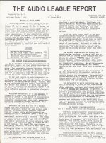
The first critical review - "The Audio League Report" October 1955 by Julian Hirsch
In many folks eyes, the late Julian Hirsch set the gold standard for objective testing of audio equipment.
This is the issue of The Audio League Report which dealt with Karlson's K15 and the relatively new twelve inch model.
In many folks eyes, the late Julian Hirsch set the gold standard for objective testing of audio equipment.
This is the issue of The Audio League Report which dealt with Karlson's K15 and the relatively new twelve inch model.
Attachments
-
 KARLSON REPORT PAGE TEN.jpg400.2 KB · Views: 191
 -
 KARLSON REPORT PAGE NINE.jpg407 KB · Views: 185
 -
 KARLSON REPORT PAGE EIGHT.jpg405.1 KB · Views: 184
 -
 KARLSON REPORT PAGE SEVEN.jpg405.1 KB · Views: 193
 -
 KARLSON REPORT PAGE SIX.jpg401.9 KB · Views: 192
 -
 KARLSON REPORT PAGE 5.jpg405.9 KB · Views: 184
 -
 KARLSON REPORT PAGE 4.jpg406.8 KB · Views: 164
 -
 KARLSON REPORT PAGE 3.jpg404.7 KB · Views: 159
 -
 KARLSON REPORT PAGE TWO.jpg402.1 KB · Views: 189
 -
 KARLSON REPORT PAGE 1.jpg395.9 KB · Views: 251
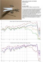
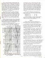
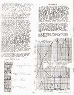
Julian Hirsch noted that different speakers exhibited pretty much the same response to each other when placed in a Karlson enslosure.
Here's an example of what I've seen
Visaton BG20. ---- Eminence Beta 10CX
Qts 0.44 ------------- 0.38
Vas 110 liter ------- 61.1 liter
Fs 38 Hz ------------- 49 Hz
Sd 214 cm2 ------- 344.9 cm2

Here's an example of what I've seen
Visaton BG20. ---- Eminence Beta 10CX
Qts 0.44 ------------- 0.38
Vas 110 liter ------- 61.1 liter
Fs 38 Hz ------------- 49 Hz
Sd 214 cm2 ------- 344.9 cm2
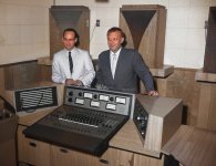
John Karlson & Reuben Guss 3-7-64 NYC FM Broadcast
Hi Fi Workbench - - Eric Towline - moderator
Guests, John Karlson and Reuben Guss.
This is a small file at ~181MB for 1 hour , 47 minutes and hopefully "acceptable". Towards the end, there are parts missing as the second generation cassette tape was damage. This show was from Roger Russell's collection.
Eric Towline mentioned to me that the tape's pitch was too high. I attempted to slow it with an online aid. That stretched time by 5 minutes but may have not noticeably lowered pitch,
By the way, here is one of Reuben Guss's loudspeaker patents:
https://patentimages.storage.googleapis.com/b8/24/b4/358d7c77ac671d/US2993091.pdf
Here's that show's audio with an assortment of Karlson related images
John Karlson and Reuben Gus Hi Fi Workbench 3-7-64 : Free Download, Borrow, and Streaming : Internet Archive
Karlson enclosures in the recording studio
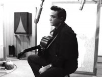
Many famous artists heard their songs' playback through Karlson K15 speakers at Owen Bradley's Quonset Hut Studio. FWIW I was told the K15 shown with Johnny Cash was loaded with an Electro-Voice SP15 fullrange 15 inch speaker which featured a "brilliance" control.
(sorry about the limitations of the free colorizer with Owen's right hand)
Attachments
Last edited:
A Improved Upload of HiFi Workbench 1964 w. John Karlson, Reuben Guss and Eric Toline
It has same 2013 audio dub from a 2nd or 3rd generation cassette set (with the original recording coming from Roger Russell's open reel collection from broadcasts). (Also the same pictures as the 2013 Internet Archive upload - btw a member of Job Ulfman's Karlson Speaker Project had sold the dubs at Ulfman's
My son Nat made a new title and slowed the audio to a more reasonable sounding gait as accumulated speed errors had things too fast.
By the time I made the 2013 upload, one of the cassettes had deteriorated to the point there were large dropouts.
There are interesting subjects and opinions discussed and the show starts with Mr. Karlson having the sound gigs for the Ford and GE 1964-65 World's Fair Exhibits. (K15 and Electro-Voice 15TRX)
Please share this video with folks if not too much trouble.
John Karlson and Reuben Guss on Hi-Fi Workbench 1964 - YouTube
John Edward Karlson (February 4, 1910 - January 18, 1973)
Reuben Guss (December 25, 1924 — October 5, 2001)
Eric Toline (April 17, 1937 - October 13, 2020)
Electro-Voice SP15 fullrange 15 inch speaker
Once, before 15-20 years I had this speaker. But only one piece.
 I measured TS parameters and transfer (was really good) and listen a bit. This is excellent sounding and measuring unit. The sound is so rich and deep. The model was with dual cone and ceramic magnet motor... Because I could not find a second unit for stereo, I sold that pice to musician/guitarist for guitar amp speaker replacement. He called me next day to express mucho thanks and satisfaction with sound of that magnificent unit.
It was very different from recent pro units. In TS params, in transfer, in mechanical way and paper membrane with soft orange linen hangings AND the sound off-course
This is maybe only non-AlNiCo spraker that I liked a lot. (Maybe Goodmans Audiom SP-15 with changed hanging less rigid. Also good like hell.)
- Home
- Loudspeakers
- Full Range
- A Karlson Compendium - Part One - "A New Approach in Loudspeaker Enclosures"