You're welcome!
Sure! Just it's much denser, so won't need [nearly] as much.
GM
Thanks again!!!!
I have tried to design a square port but is horrible: yikes:
If I do a port with a ratio of 1:10 (for aesthetics) how much I should do bigger the speaker?
Can appear problems like "blow", etc?
Thank you! 😀😀😀😀
You're welcome!
It doesn't work that way. It doesn't 'blow' ['chuff', though guess it could 'whistle' 😉]; it acts as an acoustic resistor, so make the box bigger for a given vent design and it will roll the bass off even more [increases box Q].
GM
It doesn't work that way. It doesn't 'blow' ['chuff', though guess it could 'whistle' 😉]; it acts as an acoustic resistor, so make the box bigger for a given vent design and it will roll the bass off even more [increases box Q].
GM
You're welcome!
It doesn't work that way. It doesn't 'blow' ['chuff', though guess it could 'whistle' 😉]; it acts as an acoustic resistor, so make the box bigger for a given vent design and it will roll the bass off even more [increases box Q].
GM
Therefore, is it like to have some filling material in the vent? If is, I can try to simulate it in Hornesp by adding some filling materials in the last segment.
The problem is how much I should do bigger the box? Probably is not simply to answer at this question.
Is it possible to split a single port in a multiple ports?
Instead to build a single port of 2.8cmx3.56cm = 10cm2 build 3 ports of 1.62x2.06cm = 3.33cm2 -> Atot = 3.33 x 3 = 10cm2. So the ratio of all single ports will be 1:1.273
Thank you again for your precious help.
When the project is finished I would like to ask at the moderator if I can open another thread to put all in the first post (Simulation, design, measure, photo, etc) 😀😀😀
Edit: In according to the following posts:
https://www.diyaudio.com/forums/subwoofers/119854-hornresp-476.html#post4011412
https://www.diyaudio.com/forums/subwoofers/119854-hornresp-477.html#post4013536
Seems to be that the major effect is that the effective length of a slot port it is different and there are the formula to compensate it! 😀
😀
Last edited:
Hi,
I have calculated the correction according with the formula, with slot port with a ratio 1:10, I should shorter the port of about 11.23mm.
Therefore I will try with this compensation, in addition, maybe, I will flaring a little bit the port to reduce possible chuffing. 😀😀
THank you very much!!!!
I have calculated the correction according with the formula, with slot port with a ratio 1:10, I should shorter the port of about 11.23mm.
Therefore I will try with this compensation, in addition, maybe, I will flaring a little bit the port to reduce possible chuffing. 😀😀
THank you very much!!!!
Hi,
I have buy the wood and in the next weeks I will cut the aperture for the speaker/connector and I will mount all 😀
I have buy the wood and in the next weeks I will cut the aperture for the speaker/connector and I will mount all 😀
Hi,
I have finished the first of the two speakers (now I am in the tuning phase). I have measured the response at 50cm of distance with a calibrated microphone and this is the results:

Why I obtain a so high difference? In the simulation I will predict a flat response until 70Hz-90Hz.
Thank you very much!
Why it is so different respect the simulation? In the simulation I obtain a "flat" response untile 80-70Hz.
I have finished the first of the two speakers (now I am in the tuning phase). I have measured the response at 50cm of distance with a calibrated microphone and this is the results:
Why I obtain a so high difference? In the simulation I will predict a flat response until 70Hz-90Hz.
Thank you very much!
Why it is so different respect the simulation? In the simulation I obtain a "flat" response untile 80-70Hz.
we can't see anything from that tiny picture.
Simulations will show a perfect curve in a perfect room with a perfect driver's frequency response.
As you can see in any manufacturer's data, a driver is never perfectly flat.
Also, room interactions will alter the response.
And if you are measuring at 50cm in front of the driver, you are not getting the bass output from the vent situated way down below on the floor.
Were you expecting a completely flat line? If so, you should read a bit more about audio reproduction and room interactions.
I am an idiot, you have right. If I measure at 50cm i don't take in account the output of the vent.
No, I don't expect a flat line but if I simulate a f-3db of 60Hz and in reality is 100Hz there are somethings wrong, no?
This is the new response measured in this way:
- Misure 1: 5cm of distance from the center of the speaker.
- Misure 2: 5cm of distance from the vent.

In this case, the baffle step filter is necessary? And the Zobel cell?
Why I obtain the peak at 1.7 kHz?
Thank you again 🙂
No, I don't expect a flat line but if I simulate a f-3db of 60Hz and in reality is 100Hz there are somethings wrong, no?
This is the new response measured in this way:
- Misure 1: 5cm of distance from the center of the speaker.
- Misure 2: 5cm of distance from the vent.
In this case, the baffle step filter is necessary? And the Zobel cell?
Why I obtain the peak at 1.7 kHz?
Thank you again 🙂
There are 3 measurements in that window, yet you mention only 2.
A green, a magenta and a blue.
I'm going to guess the blue is the vent. If so, it looks like there's not enough stuffing because you have a lot of output way up high.
The magenta must be the driver, and the green the overall response measured from somewhere in the room.
But, let's look at it this way... are you going to listen to the speakers at 5cm distance?
I'm guessing not.
So... place the speakers where you think it would be best.
Place the mic at the listening position (couch, chair, ...) where your head will be, at the same height of your ears, when you listen to music.
That will give you a more realistic curve that you will hear when you want to listen to music.
Please post a picture that we can actually see the numbers... You may be much younger, but my eyes can barely make out the numbers on that graph you posted.
Excuse me, yes the Blu is the vent, the magent is the speaker and green the overall response (the sum of the Blu and the Magent).
Do should I stuff with wool or for example felt? For the moment the stuff is only in the "back path".
I agree that I should measure in the ambient, but so I can not understand if the speaker is diy correctly or not.
Yes, sorry for the pictures!
Do should I stuff with wool or for example felt? For the moment the stuff is only in the "back path".
I agree that I should measure in the ambient, but so I can not understand if the speaker is diy correctly or not.
Yes, sorry for the pictures!
Do you speak French or German? might be a "lost in translation" here. 🙂
If French, I can help, my German is so far away, I lost it all.
I'm not sure I understand the term "back path".
The stuffing on a MLTL is usually spread over 75% of the line, so it goes above and below the driver. For a 3" enclosure, you could start with 70g of stuffing, the kind of you find in pillows.
Ah! I saw the Swiss flag ...
Sorry, my Italian is non-existant!
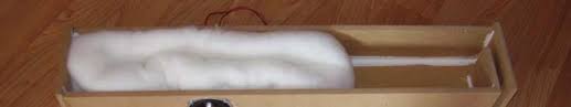
Stuffing should be 75% down the line... kind of like this:
Sorry, my Italian is non-existant!
Stuffing should be 75% down the line... kind of like this:
Seems to be that there are not much differences:

An externally hosted image should be here but it was not working when we last tested it.
Hi
I have enclosed some sims you might find interesting.🙂
Regards
Bjørn
Hi all,
I have do many test and with my design I'am not able to eliminare/reduce the peak at 100Hz-150Hz.
Therefore I would like to restart with the design xD
Maybe based on the design posted by Bjohannesen that should be better 😀
What do you think?
Thank you all for the time and help 😀
I will try to damp the vent! Do not decrease overall lowfrequency response?
Thank you very much!
Thank you very much!
You're welcome!
Of course!
It will 'bend' the response downward towards sealed. The optimum way to do it is with an impulse response and once there's no 'ringing' it's considered to be critically damped, the 4th order equivalent of a 0.5 Qtc sealed.
Frankly, it measures good enough that I'm surprised you can hear bass boost unless due to its location in room.
GM
- Home
- Loudspeakers
- Full Range
- New 3" Full range TL