I picked up a couple of these new Dayton 3 inch poly full ranges Dayton Audio PC83-8 3" Full-Range Poly Cone Driver for testing. I thought I share the results here as they were designed as a full range.
I was curious about using them as a midrange, the spec sheet indicated they should have a wide dispersion up to around 4KHz. They'll also do double duty as a test speaker an active cross over project.
The tests are geared towards off axis performance, distortion, and I did EQ them and listened for a while. The cobbled up enclosures will be sufficient for that purpose.
Index to trials:
1) Box 8L - Dayton PC83-8 (3") test results
2) Cylinder 4L - Dayton PC83-8 (3") test results
3) Box 8L + large baffle - Dayton PC83-8 (3") test results
4) MLTL - Dayton PC83-8 (3") test results
5) Omni opposed drivers - Dayton PC83-8 (3") test results
6) Le Cléac'h 7-Petal Horn - Dayton PC83-8 (3") test results
7) Le Cléac'h 11-Petal Horn - Dayton PC83-8 (3") test results
8) Fixing the Le Cléac'h Petal Horns - Dayton PC83-8 (3") test results
9) BP8 'subwoofer' to get some LF performance Dayton PC83-8 (3") test results
10 ) Bass Reflex - Dayton PC83-8 (3") test results
11 ) Tractrix Rectangular Horn - Dayton PC83-8 (3") test results
Last edited:
Box enclosure 8L
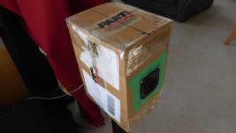
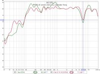
TYpically they get mounted in a skinny box, so that's the first enclosure. REW and UMIK-1 used to measure at 0.5m from center speaker, and 0.9m from ground on a stand.
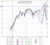
The curves up to 50deg off axis are pretty tight to 4K as advertised. My graph has the axis expanded compared to Dayton, but the 5dB dip at 2K is there. The box is 8L filled with fiberglass.
TYpically they get mounted in a skinny box, so that's the first enclosure. REW and UMIK-1 used to measure at 0.5m from center speaker, and 0.9m from ground on a stand.
The curves up to 50deg off axis are pretty tight to 4K as advertised. My graph has the axis expanded compared to Dayton, but the 5dB dip at 2K is there. The box is 8L filled with fiberglass.
Attachments
Box 8L
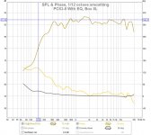
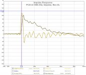
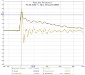
Next up is fixing the FR to flatten it a bit using APO equalizer.
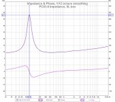
Its a single speaker, one moving part, and the IR looks fine.
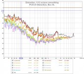
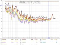
Distortion below 300Hz is high, but in the range I was interested in (800Hz-4KHz) is OK with me.
Next up is fixing the FR to flatten it a bit using APO equalizer.
Its a single speaker, one moving part, and the IR looks fine.
Distortion below 300Hz is high, but in the range I was interested in (800Hz-4KHz) is OK with me.
Attachments
Cylinder 4L
I was curious if the box shape helped (baffle gain) or hurt (diffraction) and by how much?
Should have mentioned, the IR gate (-5ms/+10ms) and 9 cycle window is used in the FR and IR plots.
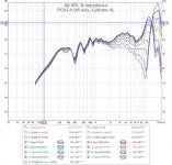
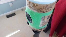
I mounted the driver in a cylinder, on the side (not end). This is suppose to have similar diffraction performance as a sphere. The speaker is mounted in a frame molded from clay to "merge" the pin cushion frame to a cylinder wall. An attempt to make it a smoother transition. It certainly has more polar symmetry than a rectangle box.
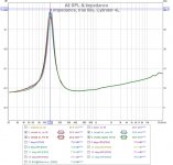
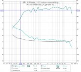
I also checked the impedance with various fills. I ended up using the fiberglass it seemed to have less FR ripple and lower impedance peak. The cylinder FR is more consistent as well. Again the entire FR is tight up to 40deg or so, but it diverges more gradually than the box.
I was curious if the box shape helped (baffle gain) or hurt (diffraction) and by how much?
Should have mentioned, the IR gate (-5ms/+10ms) and 9 cycle window is used in the FR and IR plots.
I mounted the driver in a cylinder, on the side (not end). This is suppose to have similar diffraction performance as a sphere. The speaker is mounted in a frame molded from clay to "merge" the pin cushion frame to a cylinder wall. An attempt to make it a smoother transition. It certainly has more polar symmetry than a rectangle box.
I also checked the impedance with various fills. I ended up using the fiberglass it seemed to have less FR ripple and lower impedance peak. The cylinder FR is more consistent as well. Again the entire FR is tight up to 40deg or so, but it diverges more gradually than the box.
Attachments
Cylinder 4L
Again, a little EQ to flatten out the FR using equalizer APO.
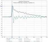
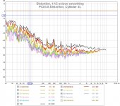
IR is well behaved like before. The distortion looks like same, flattening out at >300Hz.
Again, a little EQ to flatten out the FR using equalizer APO.
IR is well behaved like before. The distortion looks like same, flattening out at >300Hz.
Attachments
Thanks for the measurements. I have been curious about this driver as well.
I think the falloff you see below 1k is simply the baffle step. Try a big (30in wide open baffle) and see if it matches factory specs. Also, try putting mic at 0.5m and 1m off floor. Then select FDW 6-cycles gate. That removes room and floor bounce etc and lest us look at intrinsic response vs extrinsic effects of mic placement and floor bounce.
The baffle step is easily fixed with a circa 1mH parallel ~8ohm or so resistor BSC circuit.
Dayton’s measurements usually are pretty good, so I would expect it to look like this in a large baffle:
http://www.daytonaudio.com/media/resources/295-156-dayton-audio-pc83-8-specifications.pdf
Last edited:
The mic was out 0.5m from the speaker center and 0.9m off the floor.
I believe the manufacturer data sheet, so I'm not trying to refute them. Unfortunately the test conditions are rarely specified and some important details (for me) are missing.
I might try your larger baffle (30") experiment to see the effect. Maybe I can get a cheap foam board sheet from the dollar store.
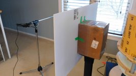
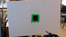
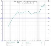
Larger baffle, to reduce bass dip
Good call @xrk971. Thanks.
I tried a larger baffle (30"x20" foam board), with your settings and the LF dip is gone. Setup pics and FR included. There is no EQ used and the previous 8L box was reused. Interesting to see the effect.
Good call @xrk971. Thanks.
I tried a larger baffle (30"x20" foam board), with your settings and the LF dip is gone. Setup pics and FR included. There is no EQ used and the previous 8L box was reused. Interesting to see the effect.
Attachments
Zaph has some notes on his test setup that I found interesting. His setup and noise floor are really good for a domestic space.
Zaph|Audio
I did a similar sequence of experiments here, where I was initially baffled (pun intended) by the notches. Even with a VERY close mic, the baffle and size still matter. I hadn't expected that.
Measurement based cone damping / treatment
Zaph|Audio
I did a similar sequence of experiments here, where I was initially baffled (pun intended) by the notches. Even with a VERY close mic, the baffle and size still matter. I hadn't expected that.
Measurement based cone damping / treatment
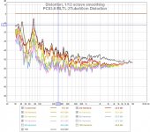
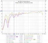
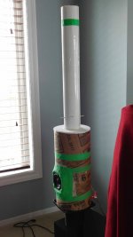
Another try, MLTL this time
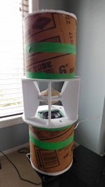
I got to thinking about another design I was looking at recently New Tube TL Omni Idea and wondering how it worked. It looks like a MLTL, as it has 2 cross section areas (circle + hex_ish), 2 lengths (circle=30cm, hex=60cm) and instead of fill, it has a lossy section of holes. It might also be the holes are strategically placed to force nulls like a woodwind instrument.
In either case I made a MLTL using offset driver, 30cm tube@6", and 50cm tube@3". HornResp predicts 50cm is best. I actually started with 72cm and measured (curious) and eventually cut back till I got to 50cm. After building it, I thought it looked like a field tractor vertical exhaust, so I added a rain flap. The sticks (bamboo skewers) are to hold the fill in position, a trick I learned from playing Kerplunk.
With some EQ for the BSC it measures quit low but understandably can't really drive that into a room. If it were on your desk it would sound quite respectable and a bargain considering its a $10US speaker. Alot of fun, discovery, experimentation and entertainment for $10US.
Attachments
Last edited:

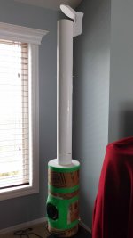
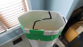
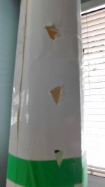
MLTL modified tail piece
As a follow on to the previous MLTL experiment, I've modified the tail piece in a similar manner to the curiosity design at New Tube TL Omni Idea .
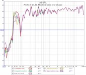
Changing the cross section from circle to hex keeps the same perimeter but reduces the area. In the extreme case I could flatten the tube and force area to zero. Adding holes effectively reduced the length of the pipe and reduced the LF performance. Both of these trials only effected the LF tuning and did not improve it. Interesting.
As a follow on to the previous MLTL experiment, I've modified the tail piece in a similar manner to the curiosity design at New Tube TL Omni Idea .
Changing the cross section from circle to hex keeps the same perimeter but reduces the area. In the extreme case I could flatten the tube and force area to zero. Adding holes effectively reduced the length of the pipe and reduced the LF performance. Both of these trials only effected the LF tuning and did not improve it. Interesting.
Attachments
Omni 2 driver
I thought I would try a few new concepts (new for me).
Idea#1 is using 2 physically opposed drivers wired in parallel to cancel vibrations. Idea#2 is a multi-cell type of omnidirectional speaker to use the cell wall as supports. I've played around with omni designs before so this is a rough "back of the envelope" design using dual reflectors.
The 2 opposed drivers really do cancel vibrations. It's odd to see the drivers bouncing around and nearly no case vibration. Bravo Newton#3.
I was quite surprised by the FR without EQ. Each enclosure is a sealed 3L +FG fill, so I'm not expecting good LF performance but most of the rest is reasonable. There is a nasty dip at 6.6Khz which could be from any number of reasons (reflection, diffraction, cell walls, etc). I think a little experimentation could find the cause and correct it. I also tried some EQ that's in the graph (in red).
Distortion is still high under 200Hz similar to before.
Attachments
- Home
- Loudspeakers
- Full Range
- Dayton PC83-8 (3") test results