And the resonances I am talking about don't have much detail, but they envelop you in a live environment. If you have ever listened to a choir in a decent size chapel or Cathederal you will understand the effect. Almost impossible to create at home from a 2 channel source, but need a challenge.
They claim x, y, z and when challenged, some do realize that those are just subjective observation and lack the objectivity such as bias control, some will double down on their claims as if their income depends on it.I'm pretty sure that those are subjective statements of preference, ie liking, so no one will blame you for ignoring them too.
 Then there are couple other types but I won't bore you with details since they are minority in numbers.
")
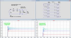
Suddenly I realised that when comparing the step response for the Townshend cable with 1 segment versus 10 segments, I should have reduced all components with a factor 10 to end with the same LRC for both.
What I did was adding 10 equal segments, meaning effectively that I made the cable 10 times as long.
For the Char Imp this makes no difference, but for a step response it does.
In the image below I have corrected this, where I still have to mention that I can't find whether the specs that Townshend provides are per foot, per meter or for their shortest cable which is 2 meter.
Anyhow, with their figures you see the step response for resp. 4, 8 and 16 Ohm for one segment and for 10 segments, where you see a faster settling time but also a larger attenuation as with one segment.
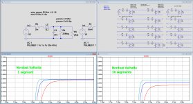
Now I did the same for the earlier mentioned Nordost Valhalla cable, also for 4, 8 and 16 Ohm
If settling time being an important feature for an LS cable, this cable behaves excellent.
Apart from somewhat more attenuation, the version with 10 segments responds almost identical to the 1 segment version.
At audio frequencies the step response is a first order low pas filter determined by the R and the L, where the C plays no role.
Hans
What I did was adding 10 equal segments, meaning effectively that I made the cable 10 times as long.
For the Char Imp this makes no difference, but for a step response it does.
In the image below I have corrected this, where I still have to mention that I can't find whether the specs that Townshend provides are per foot, per meter or for their shortest cable which is 2 meter.
Anyhow, with their figures you see the step response for resp. 4, 8 and 16 Ohm for one segment and for 10 segments, where you see a faster settling time but also a larger attenuation as with one segment.
Now I did the same for the earlier mentioned Nordost Valhalla cable, also for 4, 8 and 16 Ohm
If settling time being an important feature for an LS cable, this cable behaves excellent.
Apart from somewhat more attenuation, the version with 10 segments responds almost identical to the 1 segment version.
At audio frequencies the step response is a first order low pas filter determined by the R and the L, where the C plays no role.
Hans
Attachments
What a nice idea, I would love to be able to get the opportunity to try them once, but unfortunately no, I don’t have them.That is a nice step response graph for the Nordost. You may be the only person on the whole forum with Nordost speaker cables.
It was just to show that Char Imp is meaningless at audio frequencies because the wavelength is way larger as the cable length and therefore it cannot even behave like one.
So Townshend’s claim is not at all relevant.
But I won’t claim to have solved the question why cables may sound different.
It’s still simply black magic.
Hans
It does make a difference for the characteristic impedance: although you can stack any number of elementary, identical LPFs and get a consistent Zo (which surprised me as a small miracle), you cannot change the lump size and still get an identical result. Miracles have limits.What I did was adding 10 equal segments, meaning effectively that I made the cable 10 times as long.
For the Char Imp this makes no difference, but for a step response it does.
I showed it in one of the previous sims I posted.
For audio, it is purely academic of course, but it matters from a theoretical POV.
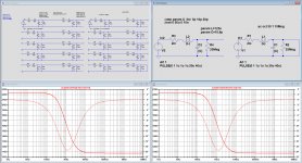
The green trace is the impedance of the lumped version; the red trace shows the values split in 12 segments.
The theory of TL applies when the elements are infinitesimally small, but it diverges with discrete, lumped elements.
Attachments
Hi Elvee,
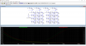
I was puzzled why the step response images showed more attenuation with 10 segments as with just one segment.
The answer is simple: an inductor has a standard series resistance of 1 mOhm.
After having corrected that to be the same between both versions, there is no difference in attenuation.
Applying that also to the transmission line equation, either by making this series resistance zero or giving the 10 segmented version a series resistance of 0.1 mOhm, results in exactly the same Char Imp figure.
See below for all series resistance set at zero.
Hans
Attachments
When Cyril Bateman (RIP) modeled a speaker cable, he used 200 segments, each with different values.It does make a difference for the characteristic impedance: although you can stack any number of elementary, identical LPFs and get a consistent Zo (which surprised me as a small miracle), you cannot change the lump size and still get an identical result. Miracles have limits.
I showed it in one of the previous sims I posted.
......................................................
Interesting paper from Wayne Kirkwood using some of Cyril Bateman’s material.
http://www.waynekirkwood.com/images/pdf/Cyril_Bateman/Bateman_Speaker_Amp_Interaction.pdf
Hans
http://www.waynekirkwood.com/images/pdf/Cyril_Bateman/Bateman_Speaker_Amp_Interaction.pdf
Hans
Thank you. It's nice to see the three papers put together. I've had them as individual ones back in 2010 IIRC.
Note with interest page 7 figure 8, the actual measurement of a 10khz sine forward and reverse wave.
Unfortunately, he did not try with a step signal, as that would have shown the settling time I speak of. I see no way using that scope to capture what happens, current scopes of course can do it. They would show how the cable "fills up" with magnetic energy to match the load impedance and not the cable impedance.
That reflection bridge toroid winding is trivial with my toroid winder.
Jn
Unfortunately, he did not try with a step signal, as that would have shown the settling time I speak of. I see no way using that scope to capture what happens, current scopes of course can do it. They would show how the cable "fills up" with magnetic energy to match the load impedance and not the cable impedance.
Just curious, do you believe that the step response of a linear time invariant system (be it a cable or any other two-port network) and its frequency response are, in any way, decoupled/independent?
- Status
- Not open for further replies.
- Home
- General Interest
- Everything Else
- Analysis of speaker cables