

Board mistakes:
I'll spin another rev of the board design to address these (but again, they are non-critical errors).
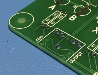
- I accidentally used the small signal trace width after the micro switches, which carry the full current of the entire circuit
 . Practically speaking, this isn't actually a problem, as the circuit draws less than 100mA, but it is a mistake nonetheless.
 - Somehow the drills were not performed for the mounting corner M3 holes and the alignment pins on the headphone jacks. I was able to work around this by using a sheet metal punch for the M3 holes, and by clipping off the plastic headphone jack alignment pins.
- As mentioned previously, the diodes immediately after the microswitches aren't needed.
I'll spin another rev of the board design to address these (but again, they are non-critical errors).
Attachments
Last edited:
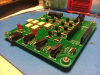
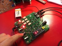
Got the board assembled, but it turns out I don't have any Arduino Nano's on hand, argh! Turns out what I had on hand are Arduino "Pro Micros", which are shorter with a different pinout. Amazon Prime can have them to me tomorrow
I really like the microswitches, first time I've used those as a user interface
Squeezing the soldering iron inbetween the relays was a bit dicey. Just barely enough room. This caught me by surprise -- not used to dealing with surface mount parts!
Turns out what I had on hand are Arduino "Pro Micros", which are shorter with a different pinout. Amazon Prime can have them to me tomorrow I really like the microswitches, first time I've used those as a user interface
Squeezing the soldering iron inbetween the relays was a bit dicey. Just barely enough room. This caught me by surprise -- not used to dealing with surface mount parts!
Attachments
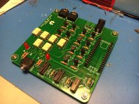
Ok, Arduino Nano's arrived, and I got the board flashed and am testing it out.
First problem: apparently I misunderstood how the input protection diodes work in an Arduino? I used 100k current limiting resistors, which still allows the full 9V to appear on the input pins, but limits the current to something which the clamping diodes can safely handle.
Well, somehow, voltage is appearing on all three input pins. 9V on the one which I'm actually pressing the switch for, and then about 5.3V on the other two. So somehow the clamping diodes are allowing voltage onto the other input pins?
The work-around is to switch from a series current limiting diode to a proper voltage divider for each input pin. Nothing a bodge can't fix.
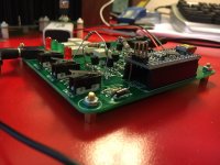
but other than that, IT WORKS! THIS IS SO COOL!!!
I plugged in two sources and played different songs just to ensure things were working as expected.
One thing I was pleased with was that even this simple way of obscuring the "reroll" (using dummy relays, and switching the relays two times) is enough to totally mask what is happening. I can't tell the difference between an "A" reroll and a "B" reroll, with or without headphones in, so this should work well for blind tests.
Also, I knew on paper that these relays were fast (4ms), but didn't appreciate just how fast it feels subjectively.
I'll get a v2 board spun up with the needed fixes, then upload all of this to github.
Attachments
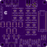
Here's v2 of the board, with the fixes.
Github (with BOM and tayda links): GitHub - pepaslabs/abx-tayda: A relay board for performing blind A/B testing of two audio sources.
Updated firmware: abx-tayda/abx.ino at main * pepaslabs/abx-tayda * GitHub
Github (with BOM and tayda links): GitHub - pepaslabs/abx-tayda: A relay board for performing blind A/B testing of two audio sources.
Updated firmware: abx-tayda/abx.ino at main * pepaslabs/abx-tayda * GitHub
Attachments
The USB port of arduino could be useful for some PC control/processing. Have you considered moving the arduino to the PCB edge so that a USB cable could be directly inserted into the port, through some enclosure wall?
That's an interesting idea, but an idea for someone else's design
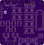
Here is v3:
GitHub - pepaslabs/abx-tayda: A relay board for performing blind A/B testing of two audio sources.
- Use RX0, TX1 pins instead of A6, A7
- Add test points to the inputs to make volume matching convenient.
GitHub - pepaslabs/abx-tayda: A relay board for performing blind A/B testing of two audio sources.
Attachments
Wow, so, not only are there no p-channel TO-92 mosfets available from tayda, even via ebay the BS250 is quite expensive ($13.78 for 50 BS250, compared to $1.40 for 50 2N7000, literally 10x as expensive).
At the cost of adding 6 additional resistors, I could convert this board to use 2N3906 PNP BJT's ($0.99 for 50, if we are sticking to ebay as a pricing metric).
At the cost of adding 6 additional resistors, I could convert this board to use 2N3906 PNP BJT's ($0.99 for 50, if we are sticking to ebay as a pricing metric).
- Status
- This old topic is closed. If you want to reopen this topic, contact a moderator using the "Report Post" button.
- Home
- Design & Build
- Equipment & Tools
- Yet another ABX box!