Capacitive load impact on distortion?
I have been working on a notch filter that can be tuned slightly to keep the notch centered on an oscillator, even when the oscillator drifts slightly or isn't accurate to begin with.
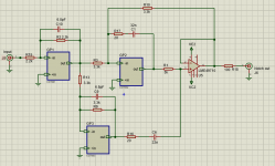
The principle has been proven, using a Bainter filter, which can be tuned with a single resistor value, without changing notch depth or Q. Basic circuit (without the tuning stuff) is attached.
The distortion however is higher than expected. From my testing it appears that it is caused by the capacitive load presented to opamps GP3 and U5. That distortion can be lowered by putting a small resistor in series with the capacitor, R16 and R17. But these resistors DO lower the notch depth so their value cannot be too high.
There is not a lot of current through those capacitors, in other words, their load is not heavy, but they do cause a phase shift between the opamp output voltage and output current I guess. Maybe that is the reason for increased distortion?
Does anyone have any experience with the impact of such capacitive load on distortion?
Does anyone know of opamps that a) are relatively insensitive to this and b) have very low distortion to begin with?
Jan
I have been working on a notch filter that can be tuned slightly to keep the notch centered on an oscillator, even when the oscillator drifts slightly or isn't accurate to begin with.
The principle has been proven, using a Bainter filter, which can be tuned with a single resistor value, without changing notch depth or Q. Basic circuit (without the tuning stuff) is attached.
The distortion however is higher than expected. From my testing it appears that it is caused by the capacitive load presented to opamps GP3 and U5. That distortion can be lowered by putting a small resistor in series with the capacitor, R16 and R17. But these resistors DO lower the notch depth so their value cannot be too high.
There is not a lot of current through those capacitors, in other words, their load is not heavy, but they do cause a phase shift between the opamp output voltage and output current I guess. Maybe that is the reason for increased distortion?
Does anyone have any experience with the impact of such capacitive load on distortion?
Does anyone know of opamps that a) are relatively insensitive to this and b) have very low distortion to begin with?
Jan
Attachments
Last edited:
A cap load that large can lower the GBW of the opamp. You will find many op-amps that oscillate with 100's of pf but will stop oscillating when you put a large cap on the output.
IIRC LT had an op-amp with an "infinite" cap load drive feature that did not increase distortion. You could quickly try to pull class A current out of the op-amp to one of the rails to simply see if being in the crossover region is part of the problem.
IIRC LT had an op-amp with an "infinite" cap load drive feature that did not increase distortion. You could quickly try to pull class A current out of the op-amp to one of the rails to simply see if being in the crossover region is part of the problem.
Last edited:
I have been working on a notch filter that can be tuned slightly to keep the notch centered on an oscillator, even when the oscillator drifts slightly or isn't accurate to begin with.
The principle has been proven, using a Bainter filter, which can be tuned with a single resistor value, without changing notch depth or Q. Basic circuit (without the tuning stuff) is attached.
The distortion however is higher than expected. From my testing it appears that it is caused by the capacitive load presented to opamps GP3 and U5. That distortion can be lowered by putting a small resistor in series with the capacitor, R16 and R17. But these resistors DO lower the notch depth so their value cannot be too high.
There is not a lot of current through those capacitors, in other words, their load is not heavy, but they do cause a phase shift between the opamp output voltage and output current I guess. Maybe that is the reason for increased distortion?
Does anyone have any experience with the impact of such capacitive load on distortion?
Does anyone know of opamps that a) are relatively insensitive to this and b) have very low distortion to begin with?
Jan
Hi Jan,
Thanks for starting this thread; it should be an interesting one.
I have always liked Bainter filters, partly because of their easy tunability (in deep contrast to the twin-T). I touch on them in the second edition of my book. However, of course, the Bainter can suffer from distortion introduced by the op amps in various ways. To your particular question, I don't have an answer off the top of my head. However, the issue of distortion caused by capacitive loading on the output of the op amps would seem equally an issue for the op amps in a state variable oscillator, since the integrator op amps have a capacitor directly from output to negative input, and that capacitor carries all of the signal current.
In a related observation, I believe that the active twin T filter that employs bootstrapping of the twin-T network ground, essentially positive feedback, can have increased distortion compared to a passive twin-T because of the small-but finite nonlinearity in the output of the op amp.
Cheers,
Bob
However, the issue of distortion caused by capacitive loading on the output of the op amps would seem equally an issue for the op amps in a state variable oscillator, since the integrator op amps have a capacitor directly from output to negative input, and that capacitor carries all of the signal current.
In one case the cap load goes to a real ground, in the other the op-amp itself is making the virtual ground. The net GBW issues are different in each case. That is a simple integrator may not oscillate but put the same cap to ground in a follower connection and it does.
Last edited:
IIRC LT had an op-amp with an "infinite" cap load drive feature that did not increase distortion. You could quickly try to pull class A current out of the op-amp to one of the rails to simply see if being in the crossover region is part of the problem.
You also had one, the AD817 & family. But that comes at the expense of OLBW, so probably not a cure for increased distortion.
I'll try the class A trick. Currently I have a proto board with three Groner/Polak opamps, doubt if xover is an issue with them.
Without cap loads I measured -160dBc on them. The Bainter as shown above doesn't get any further than -135dBc in sunshine and tailwind.
Jan
You also had one, the AD817 & family. But that comes at the expense of OLBW, so probably not a cure for increased distortion.
No the AD817 has increased distortion with cap load. What frequency notch and at levels are the op-amps in question? At 1KHz 22nF is still only ~7K at 90 degrees and the 20 Ohms you add is just about where the open loop output impedance is so I don't quite see how it improves anything. Are you sure there is no instability at any point in the internal waveforms?
The notch is at 1kHz, and I am measuring at 1V input which limits internal voltages to 2V. No instability up to 1GHz ;-) . The final summer (LME49710) has just some 10mV at the notch frequency (notch depth is about 40dB) so I assume it doesn't show any distortion compared to the rest of the circuit.
Jan
Jan
the 20 Ohms you add is just about where the open loop output impedance is so I don't quite see how it improves anything.
It did improve things with the 1st prototype before I made one with the GP opamps.
That 1st proto used the usual suspects ranging from NE5534 to AD797. All showed lower distortion with the added R in series with the cap.
In hindsight, the lower distortion *could* also be the result from the notch being less deep versus the cap load being a bit more isolated?
Jan
I have been working on a notch filter that can be tuned slightly to keep the notch centered on an oscillator, even when the oscillator drifts slightly or isn't accurate to begin with.
Are you sure you want to get to the bottom of the notch? Most modern ADCs need the fundamental knocked down just 20 or 25 dB (from 0 dBFS) to put the 2H and 3H at really low levels.
Seems like you'd need to worry about the oscillator's normal wandering returning extreme variations in amplitude as it climbs up and down the edges of the notch at its limits. And that slope is extremely steep. It think it's better to HOPE there is a detuning between the notch and oscillator so that the end result is very constant 40-50 dB attenuation. At that point, you are riding the skirt in a much flatter region as the oscillator wanders a bit.
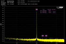
In the attached plot the ADC is an AK5397. The oscillator is nominally 6 dBV out (0 dBFS point for ADC) and then the oscillator runs through a buffered 25 dB attenuator. So, when hitting the ADC at -25 dBFS, you can see the 2H and 3H are around -155 dBFS (suggesting a perfect notch would deliver THD of 145). What would be more appealing is a flat-bottomed notch with a bottom that is -40 or -50 dB or so and a width of 10-20 Hz
Attachments
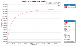
Matt, thanks for that. But my purpose is a tracking notch that follows the oscillator as it wanders or drifts slightly. Say total tracking range of 6 to 10 Hz. For a nominal 1kHz oscillator that means it could vary between say 995 and 1005Hz and the notch, at nominally -40dB, will follow it and keep it centered. The goal, as you noted, is to decrease the ADC dynamic range requirements and thus its distortion.
A flat notch with a similar width would be nice but the ones I found were always 4 or more staggered notches and pretty complex. The tracking is not that hard to do, but the issue is the distortion from the tuning system. It is much easier though than the AGC of an oscillator because the control speed can be very slow (oscillators typically drift over 10's of seconds or even minutes) and there is almost total absence of oscillator signal in the control signal. The remaining non-linearity is the inherent non-linearity of a tuneable impedance.
Jan
Attachments
Last edited:
I'd not rate an integrator as a circuit with capacitive load. IMHO, only capacitor in between output and real ground falls in this category.
I wander, if distortion comes from unbalanced input impedance seen by OPA on inverting and non-inverting input. Adding series resistors to non-inverting input (connected to ground) may clear some ambiguity.
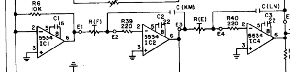
Secondly, I also noticed R39 & R40 resistors in circuits below. If we had an author of an article around, he may give an answer, otherwise just try if it makes any difference.
I wander, if distortion comes from unbalanced input impedance seen by OPA on inverting and non-inverting input. Adding series resistors to non-inverting input (connected to ground) may clear some ambiguity.
Secondly, I also noticed R39 & R40 resistors in circuits below. If we had an author of an article around, he may give an answer, otherwise just try if it makes any difference.
Attachments
I just discovered MagicianT's post and concur wholeheartedly.
I have no theories to offer about why the added resistors would improve distortion performance, but I like Scott's suggestion about loading opamp outputs experimentally to see if crossover distortion might be involved.
I do suspect that the references to capacitive loading might be generating confusion. Most commonly, discussion of capacitive loading refers to capacitance to ground that can provoke opamp oscillation. In this local context, the "load" seems to refer to the feedback network (ignoring the load of the following circuit). In the case of an integrator, the "load" is the feedback cap in series with the integrator input resistor; at high frequency the load is effectively the input resistor. Unity-gain stable opamps are inherently stable in low-frequency integrators. The situation is more complex in composite amplifiers, but if the composite has been designed for unity gain stability, it should be similarly stable in low frequency integrators.
I'd not rate an integrator as a circuit with capacitive load. IMHO, only capacitor in between output and real ground falls in this category.
I wander, if distortion comes from unbalanced input impedance seen by OPA on inverting and non-inverting input. Adding series resistors to non-inverting input (connected to ground) may clear some ambiguity.
Secondly, I also noticed R39 & R40 resistors in circuits below. If we had an author of an article around, he may give an answer, otherwise just try if it makes any difference.
The author of that article is a member here and has already posted in this thread ;-)
I believe those resistors are for stability reasons. I have used my GP opamp implementations with wildly unequal input resistances and they were clean down to -160dBc.
There is something else going on here.
I will be away a few days but intend to test the cap to ground.
Jan
Last edited:
I just discovered MagicianT's post and concur wholeheartedly.
I have no theories to offer about why the added resistors would improve distortion performance, but I like Scott's suggestion about loading opamp outputs experimentally to see if crossover distortion might be involved.
I do suspect that the references to capacitive loading might be generating confusion. Most commonly, discussion of capacitive loading refers to capacitance to ground that can provoke opamp oscillation. In this local context, the "load" seems to refer to the feedback network (ignoring the load of the following circuit). In the case of an integrator, the "load" is the feedback cap in series with the integrator input resistor; at high frequency the load is effectively the input resistor. Unity-gain stable opamps are inherently stable in low-frequency integrators. The situation is more complex in composite amplifiers, but if the composite has been designed for unity gain stability, it should be similarly stable in low frequency integrators.
The cap load is to virtual ground, and it is not clear to me that the effect of that would be different from hard ground. But I will find out.
Jan
The cap load is to virtual ground, and it is not clear to me that the effect of that would be different from hard ground. But I will find out.
Jan
The virtual ground is not ground at high frequencies, the op-amp needs finite input voltage to make an output signal.
Yes I know. But for audio frequencies, maybe a few mV max? Compared with the opamp output signal, a volt or so, for all intends that inverting input is pretty close to ground.
I agree that for high frequencies it isn't, which I guess is why it is plays a role in stability, but does it play a role regarding cap load?
Jan
I agree that for high frequencies it isn't, which I guess is why it is plays a role in stability, but does it play a role regarding cap load?
Jan
I agree that for high frequencies it isn't, which I guess is why it is plays a role in stability, but does it play a role regarding cap load?
Jan
At 1KHz the load is benign ~7K at 90 degrees and adding 20 Ohms hardly changes it, so again I see no distortion making mechanism other than the phase of the load but then the 20 Ohms should make no difference at all.
- Status
- This old topic is closed. If you want to reopen this topic, contact a moderator using the "Report Post" button.
- Home
- Design & Build
- Equipment & Tools
- Capacitive load impact on distortion