Jan I seem to recall that 2nd is non symmetrical where 3rd is symmetrical.
Yes of course, my bad. So then is my reasoning valid for the 3rd? That it can only be 0 deg or 180 deg wrt the fundamental?
Jan
Jan doesn't the AP have a monitor readout of the residual distortion? You can look at the residual on an O-scope in the time domain. If you view the fundamental on another channel you can see the phase difference. Using the add function on the scope has an interesting result. You can identify where the distortion is occurring in the waveform, e.g. crossover distortion etc.
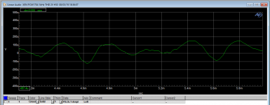
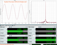
Yes, but the residual has all the harmonics and is not a 'nice' waveform. The attached is with a 1kHz fundamental (not shown, but I understand to make the phase relation visible)
What I can try is to set the FFT such that it only takes the 2nd and then convert to time domain.
Jan
What I can try is to set the FFT such that it only takes the 2nd and then convert to time domain.
Jan
Attachments
Last edited:
An issue with this thought experiment is that it requires some assumptions.
First is that the analyzer will preserve the phase relationship of the fundamental and it's harmonics. Second, that everything else involved will as well.
I know for sure the 339A does not preserve phase relationship of the harmonics to the fundamental especially if the bandwidth limit filters are engaged. I don't think any form of notch filter can either. You much consider the affect of the nyquist filter (anti aliasing) at the ADC input as well.
Last edited:
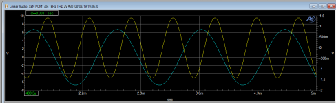
2nd and fundamental. Not sure how realistic the phase relation is.
Jan
Exactly my point.
Sure, what would you like?
John, thanks a lot for the new beta with extended distortion limit
")
Yes thanks John.
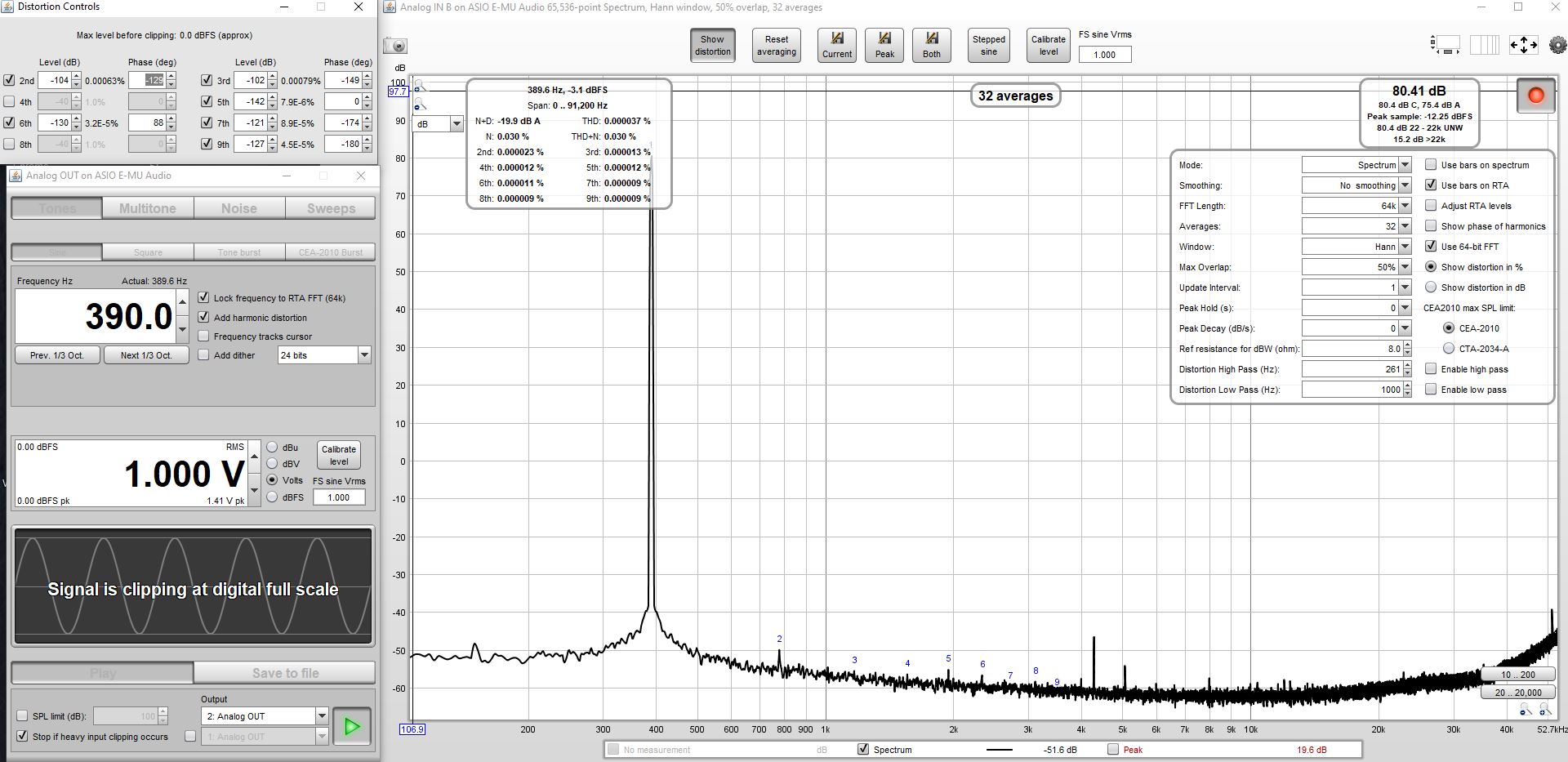
Trimming all the harmonics with a bit more finesse has reduced H2 from 0.0006% (as indicated in post #6), down to a THD of 0.000037%.
It is going to be a bit more difficult to confirm what THD is on the EMU0404 line out, as the input circuitry is going to be of some influence (line out pot was max'd, whilst input pot was at min for this test).
Just had another session checking on harmonic nulling performance with REW.
The null is slowly lost as frequency and amplitude are varied, so it's not a generic calibration set of harmonics. I could null all harmonics at 39Hz, and at 3.9kHz except the 3rd. Still, for those special times, it seems a worthy option to have handy.
The null is slowly lost as frequency and amplitude are varied, so it's not a generic calibration set of harmonics. I could null all harmonics at 39Hz, and at 3.9kHz except the 3rd. Still, for those special times, it seems a worthy option to have handy.
The distortion profile of the chain varies with frequency and amplitude, a lot. The measured harmonics (scaled with respect to the fundamental amplitude) hold only for very limited range of the amplitude. It is important to calibrate at the DUT output level (and keeping the generated amplitude, of course).
E-MU 0404 USB output and input have comparable distortion levels. Specific levels for each side are listed in the compensation tool window in https://www.diyaudio.com/forums/equ...nsation-measurement-setup-26.html#post5835569 . Output is at -1dB, input at -7.6dB, to compare each side about 6dB must be added to input(capture)-side distortions.
For this soundcard the joint-sides compensation really does not work since distortions on both sides are comparable. But there are sound devices with DAC distortion much higher than the ADC distortion and then joint-sides compensated on DAC side helps a bit.
In the end - splitting the overall distortion profile to each-side contributions is crucial for practical use.
Last edited:
One other idea I have is using the 2nd channel of the AP to generate the compensation signal to be added to the main fundamental of chan A. That comp signal can be generated as a digital multitone with individual harmonics set for amplitude and phase.
This digital multitone generator is limited to about -120dB but since its level will be at least -120dB below fundamental anyway, I am not going to worry about -240dB distortion at this point
Then add the main and comp signal and you would have a nulled analog signal. As you say, it will no doubt drift, but it should be possible to write an AP macro that nulls each fundamental in turn, then does a measurement, then null again, ad nauseam.
It's a major project, and there's a lot of unknowns to be solved first to know whether it is at all feasible, so don't expect anything useful this year
Jan
Last edited:
The pre-distortions must be phase aligned with the fundamental. It may be easier to control only one channel generating both. But trying is always the way forward
Does AP have any facility for adding post-distortions on ADC side? If so, the script could perhaps implement split-sides compensation for your AP.
Does AP have any facility for adding post-distortions on ADC side? If so, the script could perhaps implement split-sides compensation for your AP.
For the EMU0404 USB loopback, and the test conditions I used (main output pot at max, and HiZ input pot at min), the raw THD was 0.00093%. My view is that is mostly due to the output amp generating near max output (2Vrms).
Reducing the output pot by 10dB drops the dominant 2nd and 3rd harmonic levels, and similarly for another 10dB drop (any more reduction and those harmonics are in the noise floor).
Reducing the output by 10dB, but raising input pot by 10dB (to maintain the ADC input level), dropped THD to 0.00054%. The downside is the NF rises by about 5dB.
Reducing the output by another 10dB, but also raising input pot by another 10dB, saw the THD increase to 0.00085%, indicating the input stage distortion was now dominating.
For a not uncommon use, where the soundcard output is at max available level, then a simple loopback test to add in harmonic distortion to give a null will likely result in an actual line output signal with substantially lower distortion than the raw signal, even though it can't be directly measured.
Last edited:
The pre-distortions must be phase aligned with the fundamental. It may be easier to control only one channel generating both. But trying is always the way forward
Does AP have any facility for adding post-distortions on ADC side? If so, the script could perhaps implement split-sides compensation for your AP.
The ADC runs off the Reading signal which is what comes out of the notch, and post-gained by up to 60dB. The ADC distortion is negligible. Its mostly the analog stuff like the notch.
I also found out that although there are two output generator channels they really can only be independently varied in level, but will have the same source, either the analog generator or the digital generator.
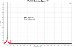
Edit: if you are looking for a target performance, the attached is a real-world measurement ...
Jan
Attachments
Last edited:
- Status
- This old topic is closed. If you want to reopen this topic, contact a moderator using the "Report Post" button.
- Home
- Design & Build
- Equipment & Tools
- Distortion analysis - a thought experiment