Sounds like an interesting test. Getting two phase locked -130 dB oscillators is difficult, but using the two phase outputs of an SVO could make it much easier.
No manufacturer will guarantee performance at the devices limits. There are some SA ADC's that claim -120 dB THD but those are difficult to use for audio.None of us are claiming -120 dB THD+N. The AP2722 only gets to -115 dB THD+N with heroic efforts. The APx series is as much as 10 dB worse.
I have been able to get -120 dB THD performance from the AK5394A as have Alex and Jens, with care and attention to detail. AKM does not claim -120 dB (and their demo board as shipped won't get there) but its possible. Even as shipped the AKD5394a is significantly better than the TI PCM4222EVM. Do not expect anything better from TI. I had a long discussion with the product manager for ADC's at TI and he simply can't justify the investment to make something better, not enough market.
I could get the ADC suprs to shift by +/-3dB on a CS5381 by shifting the phase of two inputs (L and R).
This was achieved by driving a DAC as a two channel DDS, and shifting the phase of one output.
I know it was not the oscillator as driving one input to the ADC only, leaving the other disconnected, did not produce the shift in spurs as the relative phases of the DAC were shifted. I suspect I am looking at crosstalk between the ADC channels here, with the crosstalk at the appropriate phase cancelling harmonics. A 90 degree shift in one channel neatly pushed the second harmonic down - which makes sense.
The DAC I used comes nowhere near -130dBc, which is my biggest problem with optimising the measurement system I am playing with. I am currently rebuilding the DAC taking very particular care on the output filter...
Just a question, how, and where those measurements was done ? Because I really don't understand or imagine it...
MSB SELECT DAC
MSB SELECT DAC
The test was undertaken using the following setup and process.

The phase offset to the DDS is irrelevant in terms of its harmonics - at least the digital side.
- by testing one output and shifting the phase of the other output it is possible to see if the two DDS generators are changing harmonics as a result of the phase difference between them. In this case the answer was no - shifting the relative phases of the two outputs did not alter the harmonics on the DDS output.
- with both DDS outputs going to L and R input of the CS5381, it is possible to alter the measured harmonics of one channel by a significant amount.
Note that these levels are in the -110 to -120dBc region - but that is all it takes to make a very large difference in distortion.
I spent a fair bit of time looking for coupling of noise from the supply rails into the buffer amplifier, with no effect. On the CS5381 the primary effect was on one channel - I did not record which.
if you drive one channel and leave the second shorted you can see the crosstalk on the "shorted" channel at down around these levels, so to be frank, it is not surprising to be able to show that with the right phase shift you can produce these sorts of effects.
The original point being: at such low levels even very subtle and second / third order effects start becoming important.
I am working on the V3 of the design now. So what happened to V2? Well , I made the layout for V2, but at the moment I don't intend to build that one. On V2 I made most of the minor changes I had on my list. A lot of them were simple things like component values to optimize the levels and the frequency responses. And some components were changed to slightly different types or tighter tolerances. But it still has the AK5397 ADC, which, at least at the moment, does not seem to be the best solution.
I will probably also replace the lamps used in the protection circuit with resistors. The resistors will have a lower resistance than the lamps. This can reduce the noise level of the input circuit.
I still need to verify if the protection is good enough with the resistors, but preliminary calculations seem to indicate that it will. I have an active circuit switching off the relay on the input very quickly when a high voltage is applied on the input.
On V3 I have replaced the ADC and gone back to the AK5394A. I still need to do the final optimization, since I just finished routing the board a moment ago. There are no design rule errors, but there may of course be areas, which can be optimized.
I may not even build the V3, because I will look at the possibility of making a V4! The V4 could be a version with the converters on small separate boards, giving a higher degree of flexibility.
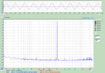
I made the attached measurement on Monday this week. It shows a loop-back measurement using the input channel, which has been modified with an AK5394A ADC. The levels chosen are probably close to where I can get the lowest distortion on DAC and ADC. To be honest there was a bit of fluctuation, so the measurement shown was one of the better ones") Most measurements were slightly worse, perhaps by 1-2 dB. But with a loop-back distortion of -133 dB I guess there is room for that!
Most measurements were slightly worse, perhaps by 1-2 dB. But with a loop-back distortion of -133 dB I guess there is room for that!
The day after I made this measurement I got the sad message about TI discontinuing a large number of IC's
In my design I use 12 x LME49990 and 4 x LME49600, which are becoming obsolete. I really like the performance of those devices. I use a few LME49720's as well, but at least that one seems to survive.
So I need to figure out if I should stay with the LME49xxx or find something else? It is of course still possible to buy the parts for the next year or so, but it is not ideal to do a design where the components are known to become EOL pretty soon.
At the moment I think that I will stay with the ones I use now, but the news about the EOL has started thoughts about possible alternatives.
Some of the alternatives may of course turn out to work even better than the current devices. But at the moment I don't know.
Some of the candidates could be:
AD797
ADA4898-1 and ADA4898-2
OPA1611 and OPA1612
No matter which one I might end up selecting one thing is for sure: the price will go up.
One of the main worries is of course distortion, particularly common mode distortion of the ones used in the input stage. According to the paper by Samuel Groner the AD797 should have a decent common mode distortion, while the OPA1611 (which I assume is the same design as the OPA211) does not do so well in this respect. The ADA4898 is a bit difficult to compare to the other ones, at least based on the data sheet. Where some of the other devices show distortion up to 100kHz the ADA4898 data sheet only shows distortion above 100 kHz! The latter does look fairly good though, so there is probably a good chance of getting a low distortion at audio frequencies.
Does anyone have experience with one or more of these devices, e.g. distortion up to 100 kHz?
Or are there other devices, which could be good candidates?
I will probably also replace the lamps used in the protection circuit with resistors. The resistors will have a lower resistance than the lamps. This can reduce the noise level of the input circuit.
I still need to verify if the protection is good enough with the resistors, but preliminary calculations seem to indicate that it will. I have an active circuit switching off the relay on the input very quickly when a high voltage is applied on the input.
On V3 I have replaced the ADC and gone back to the AK5394A. I still need to do the final optimization, since I just finished routing the board a moment ago. There are no design rule errors, but there may of course be areas, which can be optimized.
I may not even build the V3, because I will look at the possibility of making a V4! The V4 could be a version with the converters on small separate boards, giving a higher degree of flexibility.
I made the attached measurement on Monday this week. It shows a loop-back measurement using the input channel, which has been modified with an AK5394A ADC. The levels chosen are probably close to where I can get the lowest distortion on DAC and ADC. To be honest there was a bit of fluctuation, so the measurement shown was one of the better ones
Most measurements were slightly worse, perhaps by 1-2 dB. But with a loop-back distortion of -133 dB I guess there is room for that!The day after I made this measurement I got the sad message about TI discontinuing a large number of IC's
In my design I use 12 x LME49990 and 4 x LME49600, which are becoming obsolete. I really like the performance of those devices. I use a few LME49720's as well, but at least that one seems to survive.
So I need to figure out if I should stay with the LME49xxx or find something else? It is of course still possible to buy the parts for the next year or so, but it is not ideal to do a design where the components are known to become EOL pretty soon.
At the moment I think that I will stay with the ones I use now, but the news about the EOL has started thoughts about possible alternatives.
Some of the alternatives may of course turn out to work even better than the current devices. But at the moment I don't know.
Some of the candidates could be:
AD797
ADA4898-1 and ADA4898-2
OPA1611 and OPA1612
No matter which one I might end up selecting one thing is for sure: the price will go up.
One of the main worries is of course distortion, particularly common mode distortion of the ones used in the input stage. According to the paper by Samuel Groner the AD797 should have a decent common mode distortion, while the OPA1611 (which I assume is the same design as the OPA211) does not do so well in this respect. The ADA4898 is a bit difficult to compare to the other ones, at least based on the data sheet. Where some of the other devices show distortion up to 100kHz the ADA4898 data sheet only shows distortion above 100 kHz! The latter does look fairly good though, so there is probably a good chance of getting a low distortion at audio frequencies.
Does anyone have experience with one or more of these devices, e.g. distortion up to 100 kHz?
Or are there other devices, which could be good candidates?
Attachments
Were you using the LME49990 in the input stage?
I have not seen measurements for any op-amp that has less CM distortion than AD797. Of course, the only sources for CM distortion measurements seem to be Samuel Groner and Doug Self.
AD797 is not quite happy as a follower, so if you're going to use it that way I think you'll need a few extra resistors as the datasheet recommends. The ADA4898 looks good as you mention but I don't think anyone has measured it.
Yes, I (also) use the LME49990 in the input stage. In combination with an LSK389 and a cascode. The minimum gain I use is 6dB, so it is not a follower. Whether that is suffiecient to make it stable I need to check. I have actually tried the AD797 in an early prototype, where I built just the input stage (with attenuators, gain switch and protection stages).
I can't find any reference on TI's site that says the the LME49990 is end of life.
Just a reference to the LME49710 and LME49720. Reason is the process is being retired so anything manufactured under that process will be gone.
Never mind I found the list.
BTW: It's discussed here http://www.diyaudio.com/forums/headphone-systems/280990-ti-discontinue-many-ics.html
Latest suggestion from TI Eng. : single FET OPA827 .. my personal on AD797 oscillation in the MHz region...
Hp
Hello JensH,
First, thank you for this all of this great job and for your will to succeed in this hard task.
You seem to reach now very low THD level.
As you, i don't have reached better THD and noise level better than what i get with the "old" AK5394A.
So, on the paper, one much modern ADC "seem" to outperform it, the ES9102 from ESS.
I have read the full datasheet, and THD specs is -120dB@-1 dBFS and crosstalk -150dB.
It also allow 384kHz sampling rate, good thing to extend measurement bandwidth of the analyser.
These value are very good and these IC will be probably a good device for such instrument...
Although, absolutely no FFT results appear in their datasheet, i think first time i see this for an ADC...
Another big issue (i think), is that ESS seem to wanted control all communication about it
(NDA required to see any document), that is absolutely not good thing for DIY and for sharing project...
What your opinion about that ? Did you have think about ?
Another way too, that i think for a while :
Why absolutely use "audio" ADC for the analyser ?
I say that, because nowadays, some SAR ADC become as efficient as delta-sigma ADC.
You can look the LTC2378-20 that is 20bits/ 1Msps SAR ADC, the THD level
is specified to -125dB @ 2kHz and -1dBFS. Impressive, not ?
I know that two main problems occurs with these types of ADC ;
1 )- The need to make a "bridge" to convert the SPI stream in I2S format (can be done with FPGA).
The concept will be of course to easily use it with all soundcard based FFT software.
2- More wideband noise, because of no-oversampling scheme and then input LPF needed to avoid aliasing.
So, with oversampling ratio of 5 we could get 1M/5 = 200kHz equivalent sampling frequency.
That can limit the filter seriously the input LPF requirement.
I think these two issues can be solved, and finally offer some flexibility: Choosing between bandwidth or noise..
What is you opinion about that way ?
I know, that break again your job, but don't worry it is only to share my ideas about all of that,
and i think sharing all opinions is good thing.
For finished, about OPAMP to be used, i see that many OPAMP reference you gave
that require high input bias current.
Ok, their voltage noise level is extremely low, but only with very low source impedance.
I think, you could look the LT1468-2, that has very low THD even with common mode as i read
on the EDN article here.
Thank you again for sharing about this very interesting project !
Frex
Hi Frex,
Thanks for your detailed feedback. You are definitely more than welcome to share your ideas. I appreciate the suggestions and ideas put forward by other members of this forum. I may, or may not, implement the suggestions. If I implemented all the suggestions I would probably never finish!
I am not so worried about a relatively high bias current, or current noise for that matter, because I use a FET/op-amp combo, similar to what is outlined here:
Some Tips on Making a FETching Discrete Amplifier
Figure 9 looks similar to what I have, except that I use a normal potentiometer for the trimming. I kept the transistor, so I can go to a SW controlled trimming if needed, without changing the performance of the amplifier
The LT1468-2 looks rather noisy compared to the ones on my list.
I have looked at the ES9102, but as you write, it (and ESS in general) is not very DIY-friendly. I do have the data sheet, but so far I have not used the device. Lack of hard evidence about the performance, various negative comments about the performance, uncertainty about the functionality and the rather high cost of the device has kept me from trying it.
I have also considered the option of using a different kind of ADC (non-audio), but again that means additional work in terms of filters and interface as you also point out.
The many different option for the ADC (and the DAC as well) is the reason that I consider making the V4 (as suggested by other forum members), where the ADC and DAC + analog interfaces can be placed on separate boards. That will make it easier to replace the converters to upgrade or adapt to specific needs.
The ESS part looks to be discontinued and supposedly they are replacing it soon with another part that fixes all of the issues.
No doubt other issues will surface. The best news would be if they got a bit more diy friendly.
Regards
Hello JensH,
about OPAMP to be used, i see that many OPAMP reference you gave
that require high input bias current.
Ok, their voltage noise level is extremely low, but only with very low source impedance.
I think, you could look the LT1468-2, that has very low THD even with common mode as i read
on the EDN article here.
Thank you again for sharing about this very interesting project !
Frex
From experience using many new opamps, the LT1468 is my favorite 'go-to' opamp. My first choice..... over ad797 and LME ------. etc.
-RNM
- Home
- Design & Build
- Equipment & Tools
- DIY Audio Analyzer with AK5397/AK5394A and AK4490