e-ic,
I would venture to say it would not, but then I'm not and expert. I ran mine with some boards out.
Can you post some pics of it?
Or, ADC board, but is that just the small addon board?
Cheers,
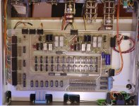
I found this of the A3 Board, look like this?
I would venture to say it would not, but then I'm not and expert. I ran mine with some boards out.
Can you post some pics of it?
Or, ADC board, but is that just the small addon board?
Cheers,
I found this of the A3 Board, look like this?
Attachments
Last edited:
The 725 through 725C all use PC edge connectors. The 725D and other more current instruments from Shibasoku use a mix of Eurocard connectors.
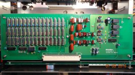
I would really like to see a picture of the 725C ADC assembly since my 725 has a failing ADC and I'll need to invent a replacement for a 30 year old ADC chip.
I would really like to see a picture of the 725C ADC assembly since my 725 has a failing ADC and I'll need to invent a replacement for a 30 year old ADC chip.
The 725C I got is some sort of hybrid.
A mix of 725B and 725C/D. The ADC has a label 725D on it.
Might sound silly, but should I encounter magic smoke if I operate the unit without the "A" boards?
Believe one of my supply voltages is off.
The unit will be confused but it should operate fine with the boards pulled. I would do it one at a time and odds on you find a dead tantalum or electrolytic on the offending board. you should have +/- 24V and +/- 15V I believe for the analog supplies. A22 has the "regurator" for the analog supplies per the manual.
I think Davada was intrigued by the 725B/C power supplies, and if I recall
kind of disappointed with the 725D power supply kind of being inferior to the
former. What did you think? Do you have pics of the 725B/C power supplies?
Mr. D.M. you are BADD, that A22 "regurator" must be a sight to see. 🙂
OIC - My badd, CYA, you included the necessary "per the manual."
Cheers,
kind of disappointed with the 725D power supply kind of being inferior to the
former. What did you think? Do you have pics of the 725B/C power supplies?
Mr. D.M. you are BADD, that A22 "regurator" must be a sight to see. 🙂
OIC - My badd, CYA, you included the necessary "per the manual."
Cheers,
Last edited:
Made some inversions by mistake.
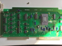
The 725D IC is on A13 board. ADC is A14.
A22 PSU. Lazy to pull out the other one with 3 regulators (78/7915 and 7805).
Powered the unit with the GPIB board installed only.
Voltages are decent, some +/-15V ones are off by .3V.
The 725D IC is on A13 board. ADC is A14.
A22 PSU. Lazy to pull out the other one with 3 regulators (78/7915 and 7805).
Powered the unit with the GPIB board installed only.
Voltages are decent, some +/-15V ones are off by .3V.
Attachments
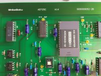


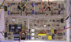
ADC can be socketed and replaced easy.
The regulators are very easy to replace, decent space around them.
Modern variants of the old 78/79 design are much better, the Vdrop across them will be higher, however the currents are small.
The regulators are very easy to replace, decent space around them.
Modern variants of the old 78/79 design are much better, the Vdrop across them will be higher, however the currents are small.
Last edited:
e-ic, Good pics.
So if the voltages are good with only the GPIB installed, then one of the others
is at fault. I assume you are going to install one at a time until you find the culprit board?
Good luck, it seems you are on your way to getting your 725C up and running.
Cheers
So if the voltages are good with only the GPIB installed, then one of the others
is at fault. I assume you are going to install one at a time until you find the culprit board?
Good luck, it seems you are on your way to getting your 725C up and running.
Cheers
What are the good ultra quiet variants of the 78/79 series of regulators?
I would assume more stable too?
Perhaps STMicros L78xx/L79xx
or maybe TIs LM78xx/LM79xx
or TIs, LM340 Series
or Analog Devices: LT1083-85
ADs say they are pin compatible,
does that mean also drop in replacement?
Nope, they need and output cap for stability,
150uf Alum 'lytic or 22uf solid tant.
Thinking out loud here.
Last edited:
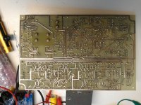
Put all modules inside. Seems to be working fine.
-----
There is one empty, between A8 and A9 if I remember correctly. It was populated on 725B however the C model does not have it.
And these 725 look like they were made by different constructors. Differences between boards, between units of same type etc..
----
LDO Low Noise variants for the monolithic ones.
What are the good ultra quiet variants of the 78/79 series of regulators?
Apart from discrete Hypex HxR12 series regulators I think that On Semi MC78xxA (note the "A" suffix) are rated to higher, 80 dB ripple rejection.
I just discovered an error in my simulation of the band elimination filter, I left off the connections of the capacitance neutralization.
Attached are updated simulation files of the A3 and the composite of the A3, A4 and A5 boards. These have the LME49990 opamps. I should probably change those to the relevant OPA's (OPA1611?). The addition make a difference and these are set up to allow some checking of the variable parameters as I figure out how to align the filters.
Attached are updated simulation files of the A3 and the composite of the A3, A4 and A5 boards. These have the LME49990 opamps. I should probably change those to the relevant OPA's (OPA1611?). The addition make a difference and these are set up to allow some checking of the variable parameters as I figure out how to align the filters.
Attachments
Demian, are your schematics 725D or older model? Davada had wrote 725D's 1st BEF is twin T circuit in this thread, instead of bridge T in 725C or older model. Also found this picture ShibaSoku Automatic Distortion Analyzer
But cap neutralizer seems is from 725B/C. U4 and CRs around it is not present in 725B/C. Even though, is C3 really tied to the point? I think that circuit block is neutralizing cap on noninverting input of U4.
Another possible error in your schematic, positive feedback path including R17, R18, U7 s' signal is taken from output of the third stage in the 725B/C. With this the shoulder of BEF become sharper.
Gentlemen,
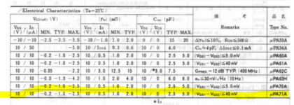
I know this is quite off topic, but while reading this thread, happened on the VP-7221A manual, which I went through. Seems it uses a dual jFet #uPA71A, it has four of them that I noticed. I have a blown channel on a B&K 2190 scope, where that part is the culprit. Has anyone ever located a good sub for that (unobtainium) part? I have been considering the LSK389x dual as a possibility? Any other suggestions? Thanks.!
I know this is quite off topic, but while reading this thread, happened on the VP-7221A manual, which I went through. Seems it uses a dual jFet #uPA71A, it has four of them that I noticed. I have a blown channel on a B&K 2190 scope, where that part is the culprit. Has anyone ever located a good sub for that (unobtainium) part? I have been considering the LSK389x dual as a possibility? Any other suggestions? Thanks.!
Shinja:
I'm working from very imperfect information. The manual's schematic (for the 725B) is not easy to follow and I believe some connections drive the cans on the relays. I have a 725 (pre A) a 725D and a AM70A which all have similar circuitry. Whether is a bridged T or a twin T is not real easy to determine from inspection and the rest of the circuit is as little changed as possible it seems. The AM70A shares a lot except the harmonic analysis done in DSP.
I'll go back through the schematic and see if I got those connections scrambled. I'll also look for that positive feedback path I overlooked. What impressed me is that the simulation actually runs quite fast. Thanks for the input.
Attached is the spec for the uPA71A. The key spec would be the capacitance and second the IDss. Too much C and the circuit won't work right on your scope. The linear Systems site is not an easy one to check specs but there should be several matches. Good luck.
Attachments
I'll send the files shortly that I have for both 725-725C and 725D. I have the unit David modified and I can open it and document as necessary.
Demian,
Thanks for the files you sent me.
I was able to obtain a copy of the AD725D operating instructions. It is approximately 75 pages and the file size is 12.1MB. I sent you a copy via e-mail a couple days ago as well as some comments about the 315B and 315C noise test sets. I am not sure if you received it.
Ed
Last edited:
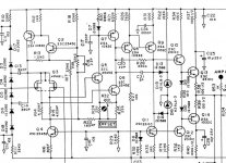
I have had a request for info on the Shibasoku 590AR oscillator. I'm sharing here because its the companion oscillator to the 725 analyzers (before the D version). Also because it shares basic circuit design with the 725's.
The 590 is a state variable oscillator with relay controlled frequency selection. The output comes directly from the second stage amp, no buffer amp. Internally it operates at 10V RMS from +/-30V supplies. It uses a passive attenuator for 1 dB and 10 dB steps. The +/- 1 dB adjustment actually adjusts the AGC reference voltage.
Adjustments without a really good analyzer will be pointless. I found a slight improvement with adjustment of the offset trimmers. The system level adjustments in the AGC are straightforward but the 10V adjustment and the "0dB adjustment do almost the same thing. Unless there is a serious level instability with frequency I would not touch the AGC circuitry. proper adjustment would be setting the sample time and sample width optimally to catch the peak of the waveform. And with no docs or instructions you could end up in a hopeless mess. Mine, which has not been touched in 30? years is flat to .01dB from 10 Hz to 100 KHz.
The circuit drawing is from the 725 but its used in the 590.
Attachments


- Home
- Design & Build
- Equipment & Tools
- ShibaSoku Automatic Distortion Analyzer